Overdriving A Pixel Of A Matrix Display

a technology of matrix display and overdrive circuit, which is applied in the direction of electric digital data processing, instruments, computing, etc., can solve the problems of overshooting or undershooting in the optical state transition of the pixel, not all optical transitions can be completed, and the start value of the next frame is incorrect, so as to achieve a simple feedback overdrive

Inactive Publication Date: 2008-10-02
KONINKLIJKE PHILIPS ELECTRONICS NV
View PDF1 Cites 5 Cited by
  • Summary
  • Abstract
  • Description
  • Claims
  • Application Information

AI Technical Summary

Benefits of technology

[0007]It is an object of the invention to provide a simpler feedback overdrive.

Problems solved by technology

Due to the practical limitation that the drive level will have a minimum drive value and a maximum drive value, not all optical transitions can be completed within one frame period even if the minimum drive or the maximum drive value is supplied to the pixel.
Consequently, some of the gray values stored in the frame buffer do not represent the actual optical state of the pixels at the end of the present frame and thus provide an incorrect start value for the next frame.
This error may either lead to too much or too little overdrive in the next frame, and thus may give rise to an overshoot or undershoot in the optical state transition of the pixel.
Although the feedback overdrive has an improved performance with respect to the feed-forward overdrive, its implementation requires a high amount of storage or complicate functions.

Method used


Image

  • Overdriving A Pixel Of A Matrix Display
  • Overdriving A Pixel Of A Matrix Display
  • Overdriving A Pixel Of A Matrix Display

Examples


Embodiment Construction

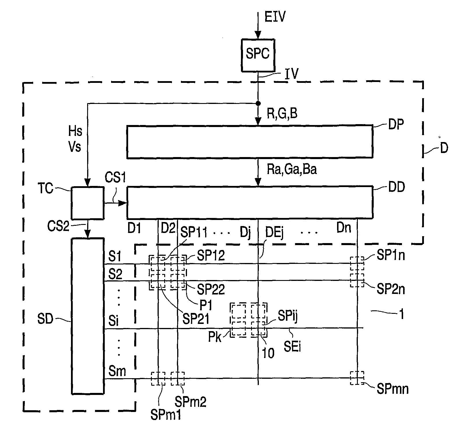
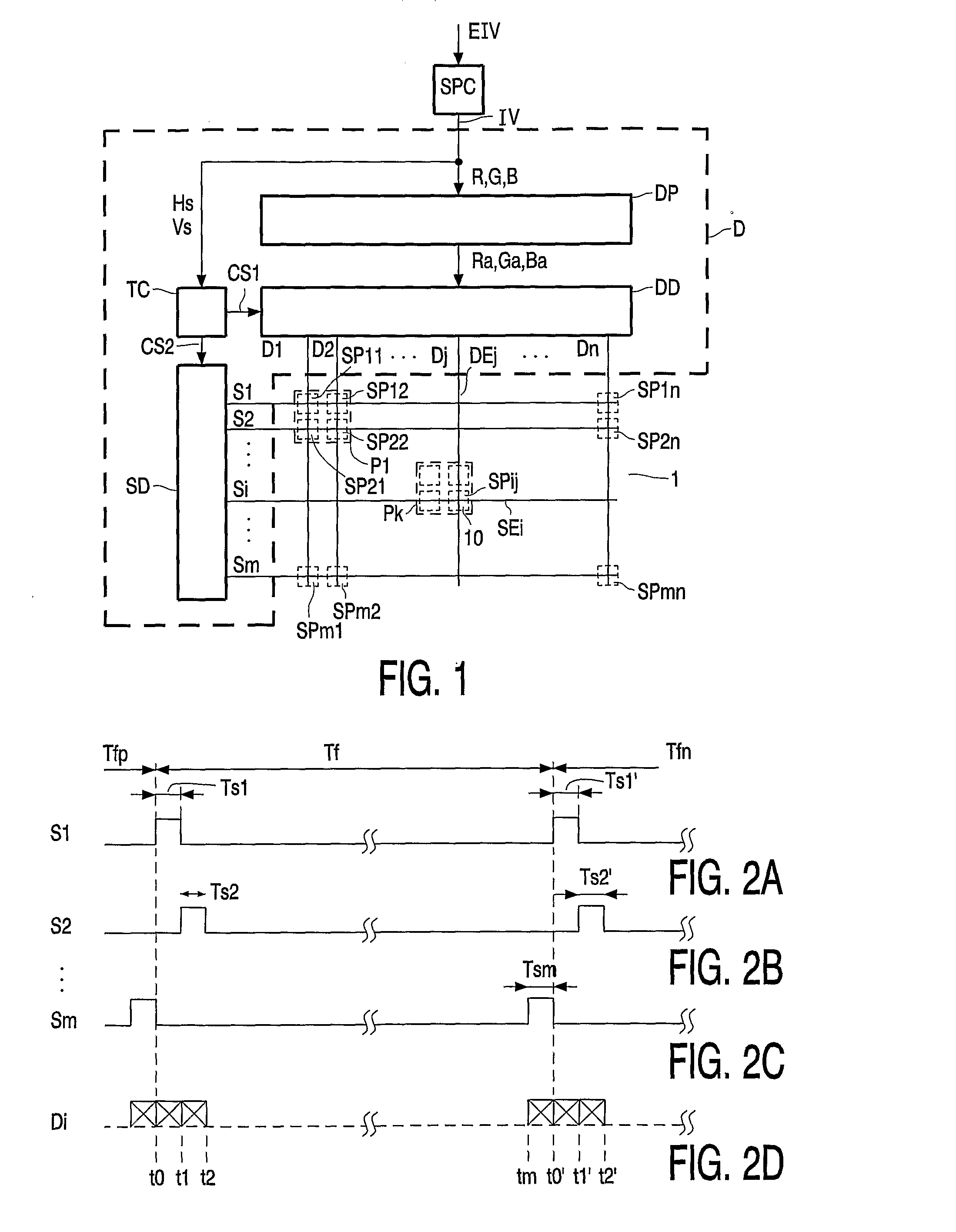
[0034]FIG. 1 shows a block diagram of a matrix display apparatus. The matrix display apparatus comprises signal processing circuitry SPC and a matrix display device comprising a driver D and a matrix display panel 1. The matrix display panel 1 comprises sub-pixels SPij (SP11, SP12, SP21, SP22, SP1n, SP2n, SPm1, SPm2, SPmn) which are associated with intersecting select electrodes SEi and data electrodes DEj. The index i indicates the select electrode SEi involved, the index j indicates the data electrode DEj involved. By way of example only, the matrix display panel 1 shown in FIG. 1 has square sub-pixels SPij and pixels Pk which each comprise four sub-pixels SPij (the pixel P1 indicated comprises the sub-pixels SP11, SP12, SP21, and SP22). The sub-pixels SPij may have other dimensions such as oblong rectangles; the pixels Pk may comprise less or more than three sub-pixels SPij. The matrix, although having generally a rectangular structure, may have any structure. The four sub-pixels...


PUM


Abstract

An overdrive circuit (20) for a display panel (1) comprising a pixel (10) having inertia further comprises a table look up circuit (24) or a function circuit (24) which receives a start value (SV) and a desired value (DV) being either an input value (IV) indicating an image to be displayed, or a clipped value (CV) and which supplies an overdrive value (OV) to the pixel (10). A substituting circuit (30) substitutes the input value (IV) by a reachable response within one predetermined period (Tf) starting from the start value (SV) to obtain the clipped value (CV). A memory (23) receives the clipped value (CV) to supply the start value (SV) which is the clipped value (CV) delayed over the one predetermined period (Tf). The substituting circuit (30) comprises a table look up circuit or a function circuit (22) which indicates for the start value (SV) a corresponding minimum value (MI) reached from the start value (SV) within one predetermined period (Tf) if a minimum drive value (MID) is applied to the pixel (10), and a corresponding maximum value (MS) reached from the start value (SV) within one predetermined period (Tf) if a maximum drive value (MAD) is applied to the pixel (10).

Description

FIELD OF THE INVENTION[0001]The invention relates to an overdrive circuit for a display panel, to a display device and display apparatus comprising the overdrive circuit, and to a method of overdriving a pixel of a display panel.BACKGROUND OF THE INVENTION[0002]Liquid Crystal Displays (further referred to as LCD's) are known to exhibit an imperfect temporal optical response, see N. Fisekovic et al., Improved motion picture Quality of AM-LCD's using scanning backlight, IDW2001, pp. 1637-1640. A step in the input signal of successive video frames does not lead to a respective step in the luminance output. Instead, the LCD shows considerable latency, the luminance output slowly approaches the desired value. A method called overdrive is used to speed up the response of the LCD. For example, if a brightness transition to a higher brightness is desired, a higher data level or data value than the data value required for reaching in the end the desired brightness value is supplied to the LC...

Claims


Application Information

Patent Timeline
Patent Type & Authority Applications(United States)
IPC IPC(8): G09G5/00G09G3/36
CPCG09G3/3648G09G2320/0252G09G2320/0285G09G2340/16G02F1/133G09G3/20G09G3/36G09G3/38
Inventor KLOMPENHOUWER, MICHIEL ADRIAANSZOONVELTHOVEN, LEO JAN
Owner KONINKLIJKE PHILIPS ELECTRONICS NV
Why Eureka
Try Eureka