Variable frequency electrostatic drive

a variable frequency electrostatic drive and electrostatic motor technology, applied in the direction of electrostatic generator/motor, electrostatic motor, electrostatic generator details, etc., can solve the problems of inability to extract maximum torque per volt or field oriented control in dynamic variable speed situations, and achieve improved electrostatic motor control, efficient torque production, and improved characterization of the necessary current vector angle

Active Publication Date: 2018-05-22
WISCONSIN ALUMNI RES FOUND
View PDF15 Cites 4 Cited by
  • Summary
  • Abstract
  • Description
  • Claims
  • Application Information

AI Technical Summary

Benefits of technology

[0007]The present inventors have developed an electrical drive for an electrostatic motor that can tailor the stator voltages precisely to the rotor position to provide greatly enhanced electrostatic motor control. Current-source drivers are used to adapt the field control transformation techniques of electromagnetic motors to the electrostatic domain. The novel saliency of an electrostatic motor is modeled to provide for improved characteri

Problems solved by technology

Prior techniques for electrostatic motors were unable to extract maximum tor

Method used


Image

  • Variable frequency electrostatic drive
  • Variable frequency electrostatic drive
  • Variable frequency electrostatic drive

Examples


Embodiment Construction

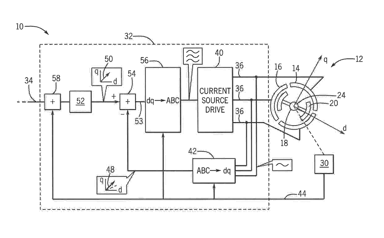
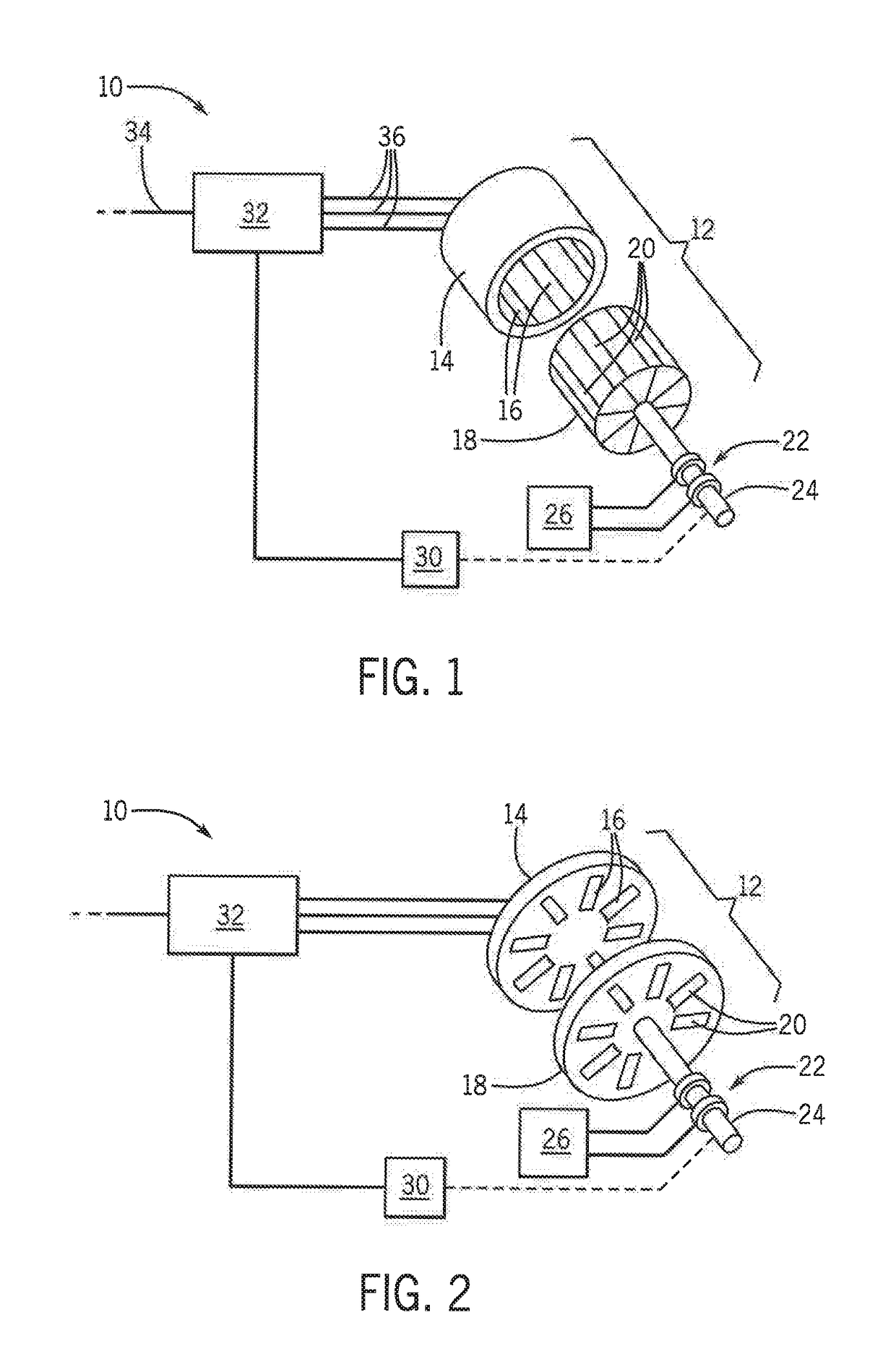
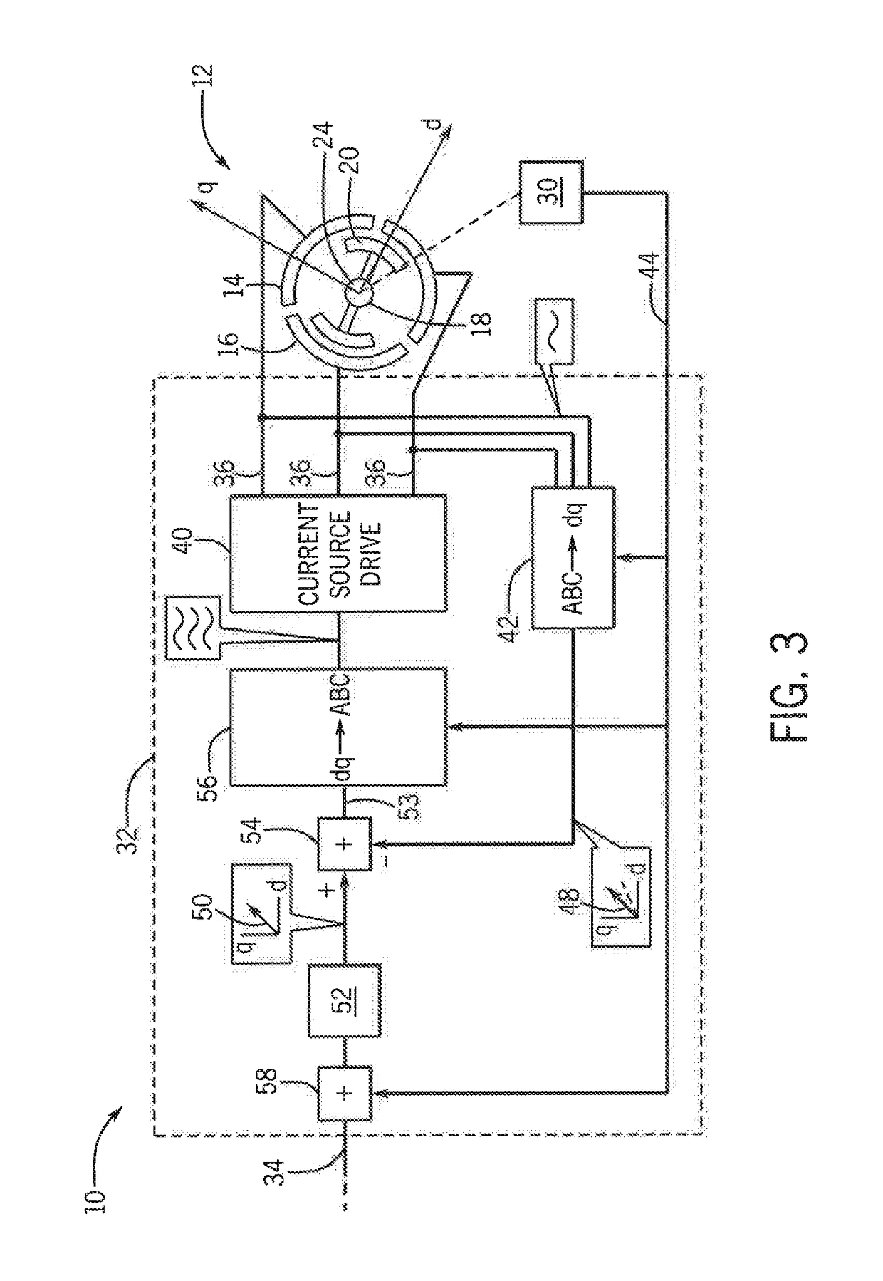
[0043]Referring now to FIG. 1, an electrostatic drive system 10 may include an electrostatic motor 12 having a generally cylindrical stator 14 supporting internal, longitudinally extending and circumferentially displaced stator electrodes 16. Fitting within the stator 14 is a rotor 18 having corresponding, outwardly exposed longitudinally extending and circumferentially displaced rotor electrodes 20 interacting with the stator electrodes 16 when the rotor 18 is positioned within the stator 14.

[0044]In an alternative design, shown in FIG. 2, the stator 14 may be one or more disk-shaped plates having radially extending, circumferentially displaced stator electrodes 16 interacting with corresponding radially extending, circumferentially displaced rotor electrodes 20 on a corresponding disk-shaped rotor 18 positioned adjacent to the disk-shaped stator 14 for interaction therewith.

[0045]Motors of this type are described in U.S. Pat. No. 9,184,676 as well as applications 2016 / 0211775 and ...


PUM


Abstract

A variable speed drive for an electrostatic motor provides feedback control by conversion of measured current phases provided to the motor into a vector in a rotating rotor framework. This vector is used for evaluating corrective voltages and then reconverted to a non-rotating framework for application to the motor electrodes. Current-source drive circuits provide current stabilized outputs making such sophisticated control tractable.

Description

CROSS-REFERENCE TO RELATED APPLICATIONS[0001]This application is a continuation-in-part of U.S. patent application Ser. No. 15 / 453,347 filed Mar. 8, 2017 and hereby incorporated by reference.STATEMENT REGARDING FEDERALLY SPONSORED RESEARCH OR DEVELOPMENT[0002]This invention was made with government support under 1452230 awarded by the National Science Foundation. The government has certain rights in the invention.BACKGROUND OF THE INVENTION[0003]The present invention relates to electrostatic motors and in particular to a drive providing electrical power to an electrostatic motor.[0004]Electrostatic motors operate by exploiting forces generated by electrical fields on a respective stator and rotor, for example, as established on opposed plates on the stator and rotor. Electrostatic motors may be distinguished from conventional electromagnetic motors which exploit forces generated by interacting magnetic fields generated by the stator and rotor, for example, generated by current-carry...

Claims


Application Information

Patent Timeline
IPC IPC(8): H01L41/04H02N1/00
CPCH02N1/008H02N1/004
Inventor GHULE, ADITYA N.GE, BAOYUNLUDOIS, DANIEL COLIN
Owner WISCONSIN ALUMNI RES FOUND
Why Eureka
Try Eureka