Flood water barrier

a technology of floodwater barrier and sand bag wall, which is applied in the direction of buttress dam, marine site engineering, shutters/movable grilles, etc., can solve the problems of damage to the panel, difficult to push the panel into the barrier, and difficult to create the sand bag wall

Inactive Publication Date: 2013-10-17
OSBORNE TOM
View PDF3 Cites 25 Cited by
  • Summary
  • Abstract
  • Description
  • Claims
  • Application Information

AI Technical Summary

Problems solved by technology

Flood waters from torrential rains, hurricanes, rising rivers and high tides cause damage.
They particularly cause damage if they approach or enter the doorways or ground level windows of a building.
While this structure and method has been satisfactory, it suffers from the disadvantages that the creation of the sand bag wall is difficult, arduous and time consuming, requiring the lifting and maneuvering of heavy sand bags into position.
Furthermore, even once the sand bag barrier has been constructed, it is not completely water tight and may allow water to seep either through the bag or through the space between adjacent bags.
This prior art solution has been sa

Method used


Image

  • Flood water barrier
  • Flood water barrier
  • Flood water barrier

Examples


Embodiment Construction

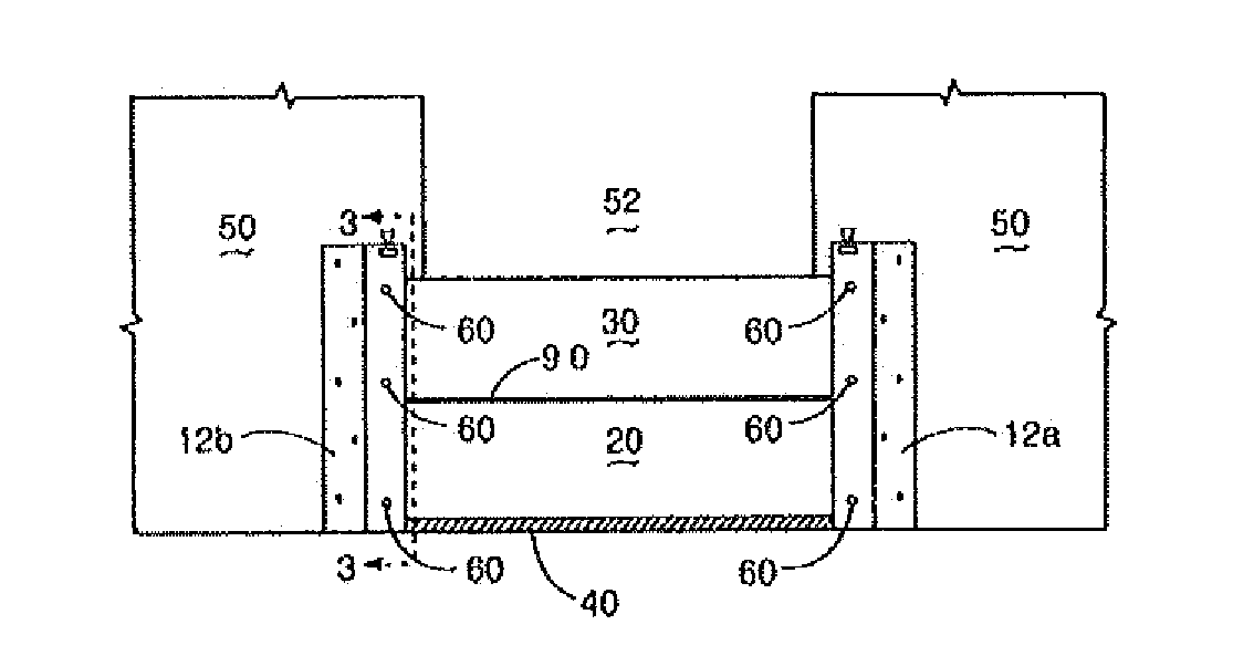
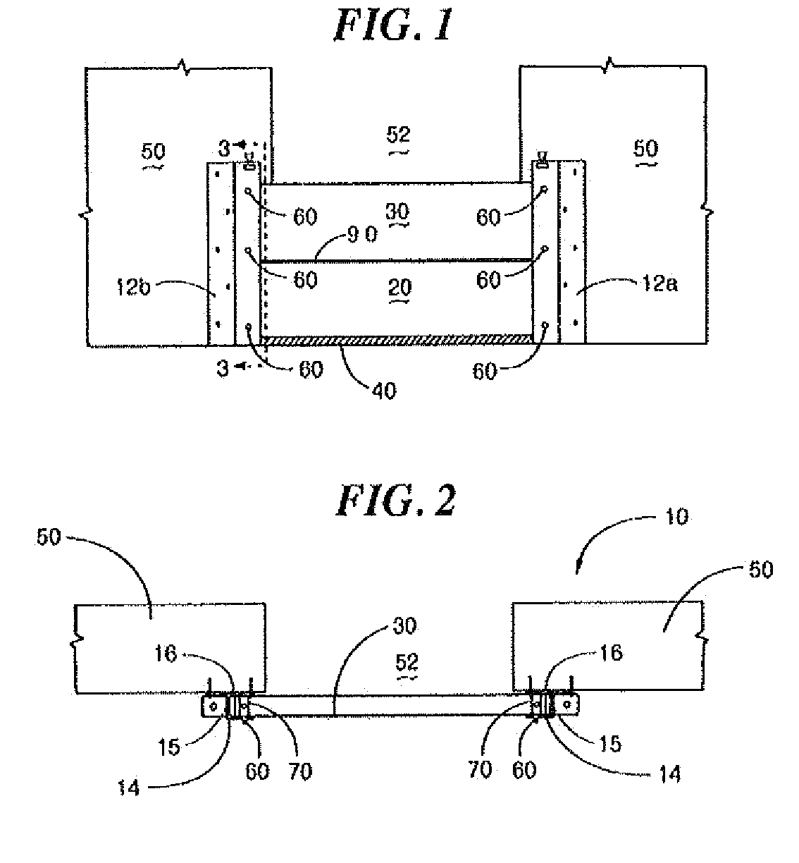
[0017]Reference is made to FIGS. 1-5 in which a flood barrier system, generally indicated as 10, is shown. Flood barrier system 10 includes a first support member 12a and second support member 12b which are spaced from each other in facing relationship. The structure of support 12b is the mirror image of support member 12a and therefore for ease of description only the structure of support 12b will be described below.

[0018]System 10 includes a first barrier member 20 which is receivably disposed between support members 12a, 12b. At least a second barrier member 30 is disposed in stacked relationship with first barrier member 20 between support members 12a, 12b to form a barrier wall.

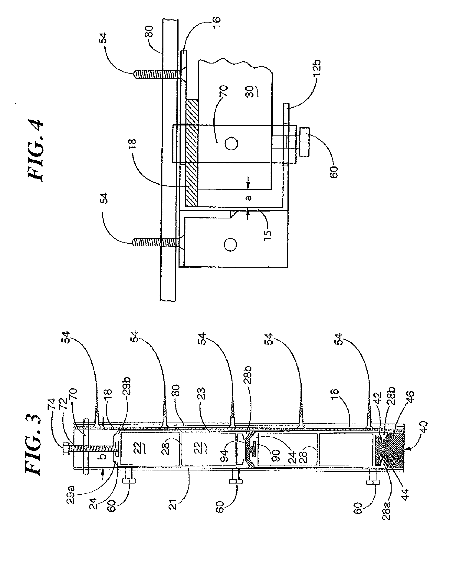
[0019]As seen specifically in FIG. 3 support member 12b includes a front wall 14 and a rear wall 16 each extending from a backwall 15, and spaced across a gap b to have a substantially C-shaped (FIG. 4) channel formed therein

[0020]System 10, in one non-limiting embodiment, includes an embedded plate 80 w...


PUM


Abstract

A flood barrier protection system has a first barrier support member having a channel therein. A second barrier member spaced from the first support member having a channel therein. A barrier member disposed within both channels is sealingly engageable with one surface of each the support member. The barrier member has a rigid front wall and a rigid rear wall spaced across a gap form each other to form a hollow body open at at least one end. An upper engaging portion and a lower engaging portion each extend from the hollow body in opposite directions.

Description

BACKGROUND OF THE INVENTION[0001]The present invention is directed to a system for preventing flood water from reaching an entry point to a building, and in particular, to a system which utilizes the weight of the oncoming water to increase the impermeability of the system to the oncoming water.[0002]Flood waters from torrential rains, hurricanes, rising rivers and high tides cause damage. They particularly cause damage if they approach or enter the doorways or ground level windows of a building.[0003]A number of methods are known for reducing the risk of flood damage to a building. The most common of these methods is to stack sand bags against the particular entry point of the building. While this structure and method has been satisfactory, it suffers from the disadvantages that the creation of the sand bag wall is difficult, arduous and time consuming, requiring the lifting and maneuvering of heavy sand bags into position. Furthermore, even once the sand bag barrier has been const...

Claims


Application Information

Patent Timeline
IPC IPC(8): E02B7/14
CPCE06B9/02E06B2009/007
Inventor OSBORNE, TOM
Owner OSBORNE TOM
Why Eureka
Try Eureka