
Method and apparatus for directional proxmity detection

a directional proxmity and detection method technology, applied in the field of wireless devices, can solve the problems of not having the capability of each mobile station to detect the location and proximity of another mobile station

Inactive Publication Date: 2013-10-24
INTEL CORP
View PDF13 Cites 135 Cited by
  • Summary
  • Abstract
  • Description
  • Claims
  • Application Information

AI Technical Summary

Benefits of technology

This patent describes a wireless device that can detect the location and proximity of other wireless devices using a phased array antenna system with a radiation pattern beam. The device can use a search strategy to optimize the process of detecting other wireless devices and reduce noise. The device can communicate with multiple wireless networks and can include various electronic devices such as computers, phones, and medical devices. The patent also describes the use of modulation techniques and communication standards for wireless communication. The technical effects of this patent include improved directional proximity detection, improved search strategy for detecting other wireless devices, and improved communication with multiple wireless networks.

Problems solved by technology

However, each mobile station does not have the capability to detect the location and proximity of another mobile station.

Method used


Image

  • Method and apparatus for directional proxmity detection
  • Method and apparatus for directional proxmity detection
  • Method and apparatus for directional proxmity detection

Examples


Embodiment Construction

[0009]Embodiments of the invention described herein are illustrated by way of example and not by way of limitation in the accompanying figures. For simplicity and clarity of illustration, elements illustrated in the figures are not necessarily drawn to scale. For example, the dimensions of some elements may be exaggerated relative to other elements for clarity. Further, where considered appropriate, reference numerals have been repeated among the figures to indicate corresponding or analogous elements. Reference in the specification to “one embodiment” or “an embodiment” of the invention means that a particular feature, structure, or characteristic described in connection with the embodiment is included in at least one embodiment of the invention. Thus, the appearances of the phrase “in one embodiment” in various places throughout the specification are not necessarily all referring to the same embodiment.

[0010]Embodiments of the invention provide a method and apparatus to facilitate...


PUM


Abstract

A method and apparatus to facilitate directional proximity detection by a wireless device. In one embodiment of the invention, the wireless device has a phased array antenna system that facilitates the directional detection of other wireless device(s). For example, in one embodiment of the invention, the phased array antenna system of the wireless device uses a radiation pattern beam that circumrotates the wireless device to detect the proximity and location of other wireless devices. In another example, in one embodiment of the invention, the wireless device uses a search strategy to optimize the process to detect the proximity and location of other wireless devices. The search strategy may adjust the radiation pattern beam to any desired angle to detect the proximity and location of other wireless devices.

Description

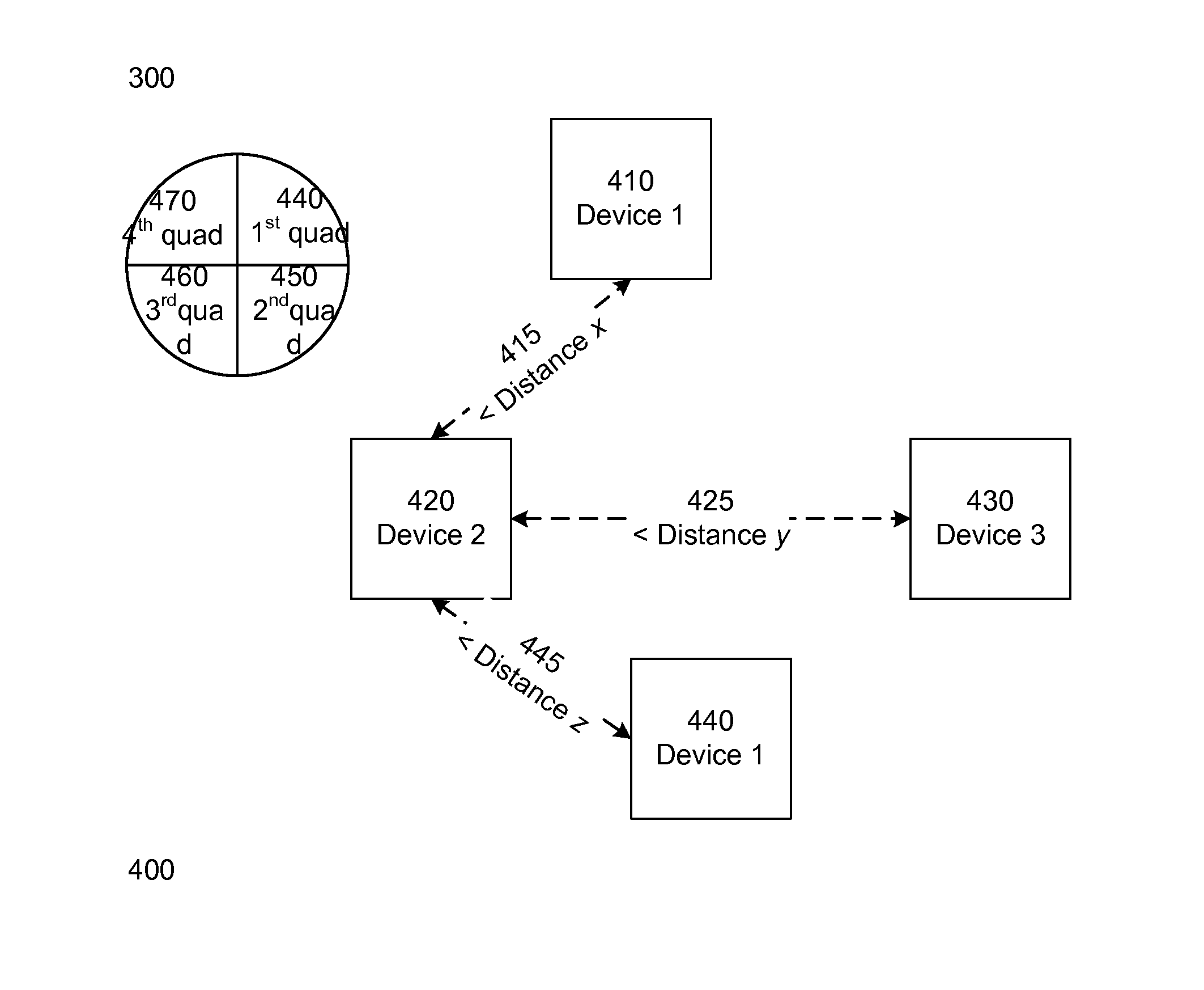
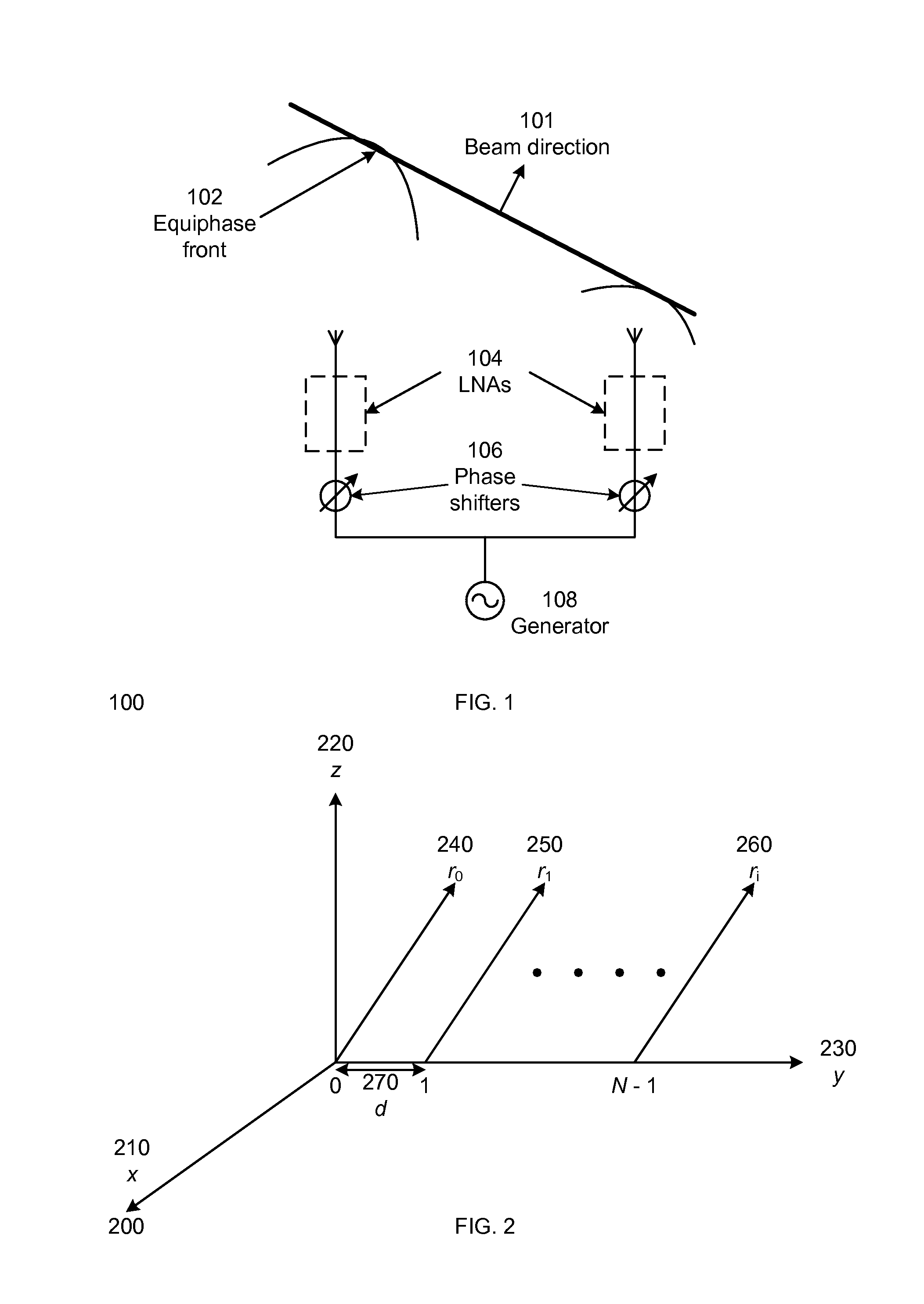
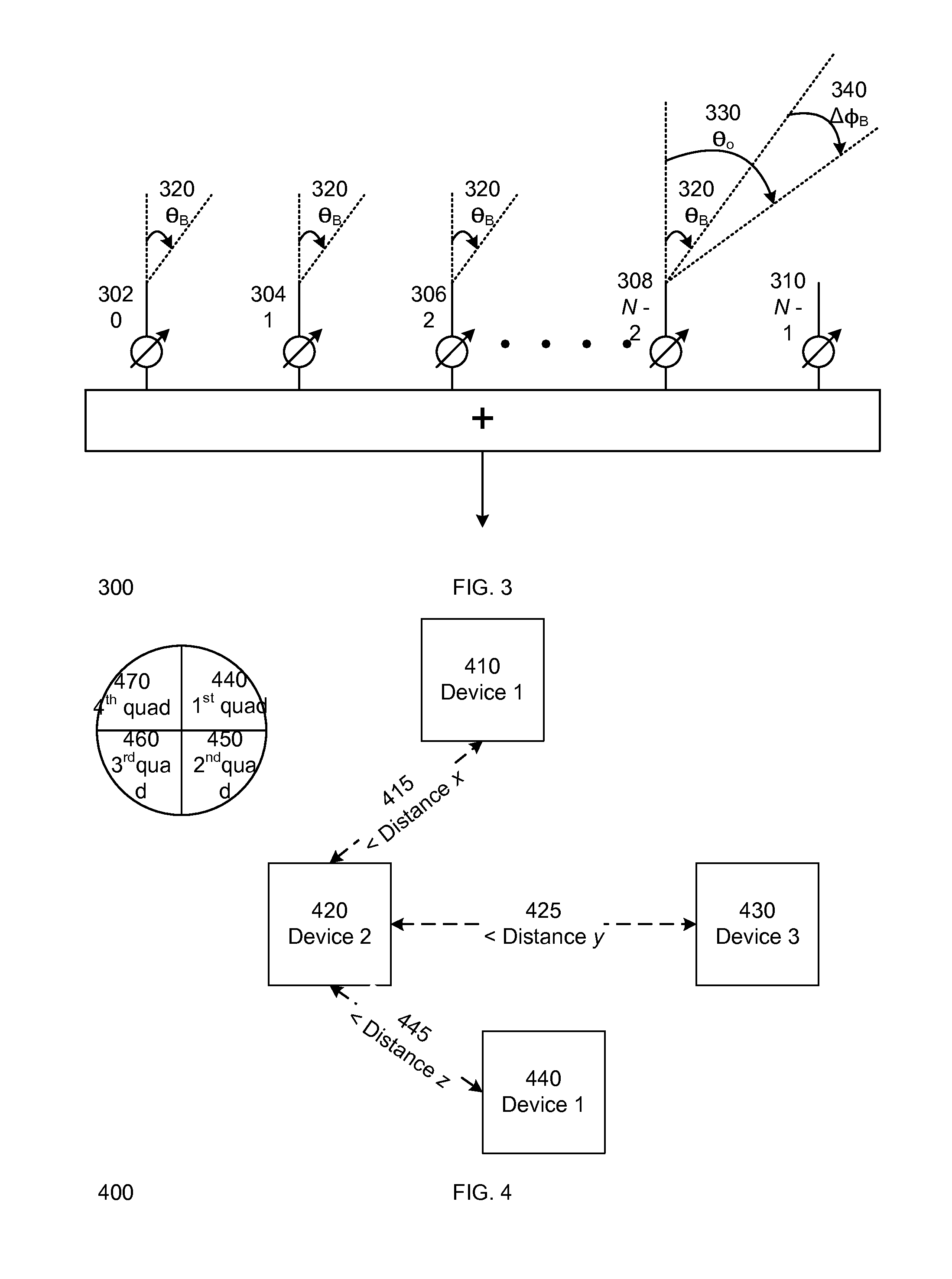
FIELD OF THE INVENTION[0001]This invention relates to a wireless device, and more specifically but not exclusively, to a method and apparatus to facilitate directional proximity detection by the wireless device.BACKGROUND DESCRIPTION[0002]In a wireless network, the mobile stations are able to communicate with each other using a wireless communication protocol. However, each mobile station does not have the capability to detect the location and proximity of another mobile station.BRIEF DESCRIPTION OF THE DRAWINGS[0003]The features and advantages of embodiments of the invention will become apparent from the following detailed description of the subject matter in which:[0004]FIG. 1 illustrates an elementary antenna array in accordance with one embodiment of the invention;[0005]FIG. 2 illustrates a linear phase antenna array in accordance with one embodiment of the invention;[0006]FIG. 3 illustrates the direction of the beam of the antenna array in accordance with one embodiment of the ...

Claims


Application Information

Patent Timeline
IPC IPC(8): H01Q3/36
CPCH01Q3/36H01Q1/2266G01S5/0295
Inventor XIA, FANLIPMAN, JUSTIN
Owner INTEL CORP
Learn More