Automatic tracking apparatus

a tracking apparatus and automatic technology, applied in the field of automatic tracking apparatus, can solve the problems of object getting out of the screen, inability to prevent phenomenon, and possibility of losing track of obj

Active Publication Date: 2013-10-24
CANON KK
View PDF1 Cites 7 Cited by
  • Summary
  • Abstract
  • Description
  • Claims
  • Application Information

AI Technical Summary

Benefits of technology

[0007]The present invention provides an automatic tracking apparatus that prevents a malfunction of losing track of an object owing to the object being out of a screen

Problems solved by technology

According to the conventional art disclosed. it Japanese Patent Application Laid-Open No. 2001-169170, when the object moves from the center at high speed, the object gets out of the screen because the dead zone is wide; there

Method used


Image

  • Automatic tracking apparatus
  • Automatic tracking apparatus
  • Automatic tracking apparatus

Examples


embodiment 1

[0047]Hereinafter, referring to FIG. 1, a configuration according to a first embodiment of the present invention will be described.

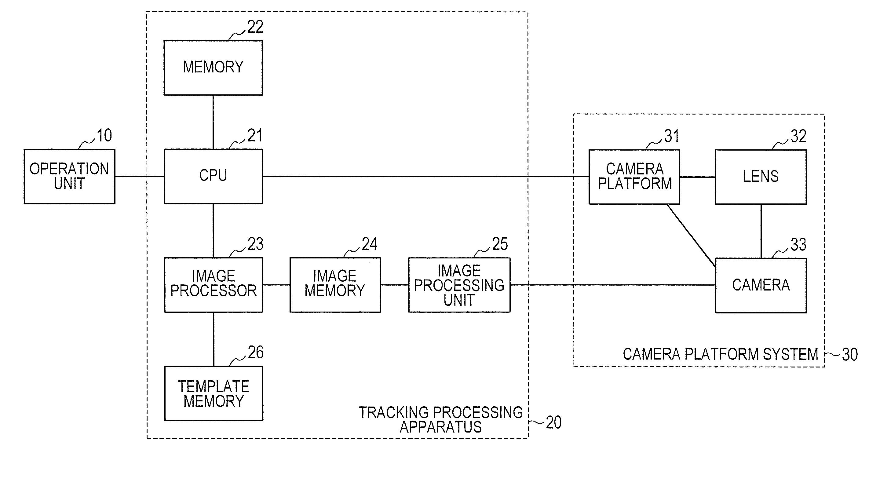
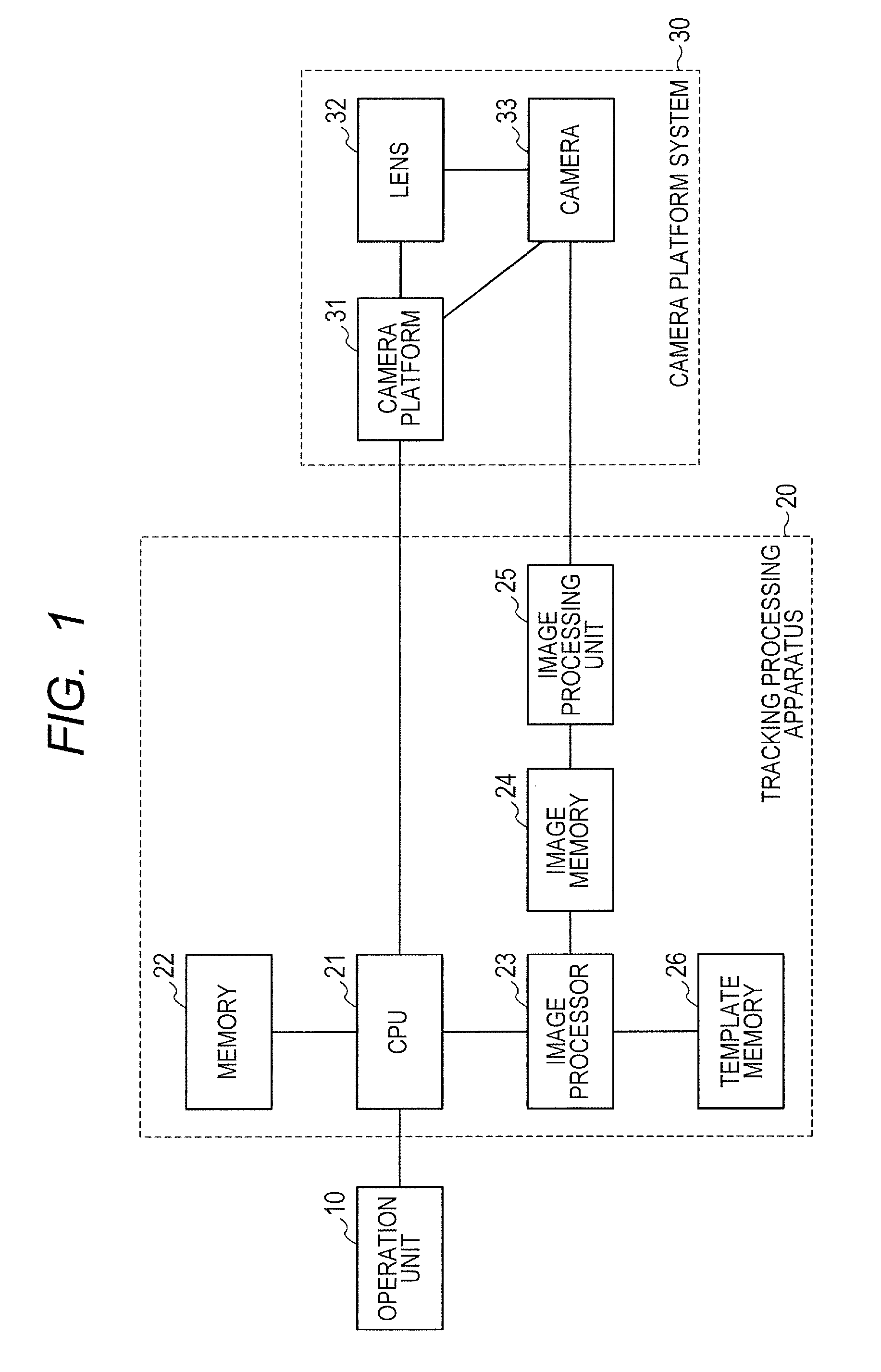
[0048]An automatic tracking system of this embodiment includes an operation unit 10, a tracking processing apparatus 20 and a camera platform system 30. An operator operates the operation unit 10, and remotely operates the camera platform system 30, thereby an image with a desired angle of view to be acquired. The operation unit 10 and the camera platform system 30 are connected to each other via the tracking processing apparatus 20. During stop of the tracking operation, a signal from the operation unit 10 is sent as it is to the camera platform system 30. In contrast, during automatic tracking, the tracking processing apparatus 20 performs processes for automatic tracking based on an image signal, and sends an appropriate control signal to the camera platform system 30, thereby tracking an object which is to be tracked.

[0049]The camera platform system ...

embodiment 2

[0062]A second embodiment of the present invention will hereinafter be described.

[0063]The configuration is analogous to that of Embodiment 1 illustrated in FIG. 1. Images of the same object are stored in the template memory 26 in association with rotation angle θy about a prescribed axis y were the images are shot in every 45 degrees of the rotation angle respectively as illustrated in FIG. 9. Furthermore, in the memory 22, conditional expressions are stored which uniquely determines the tracking prohibition area according to the rotation angles, θy and θz, of the object on axes in two directions as illustrated in FIG. 10. In this embodiment, two directions defining the respective two rotation angles are the y direction, which is one of the axial direction of pan scanning and the up-and-down direction on the image pickup screen, and the z direction, which is perpendicular to the image pickup screen; rotation angles θy and θz for the respective rotations about y and z axes are exemp...

embodiment 3

[0070]A third embodiment of the present invention will hereinafter be described.

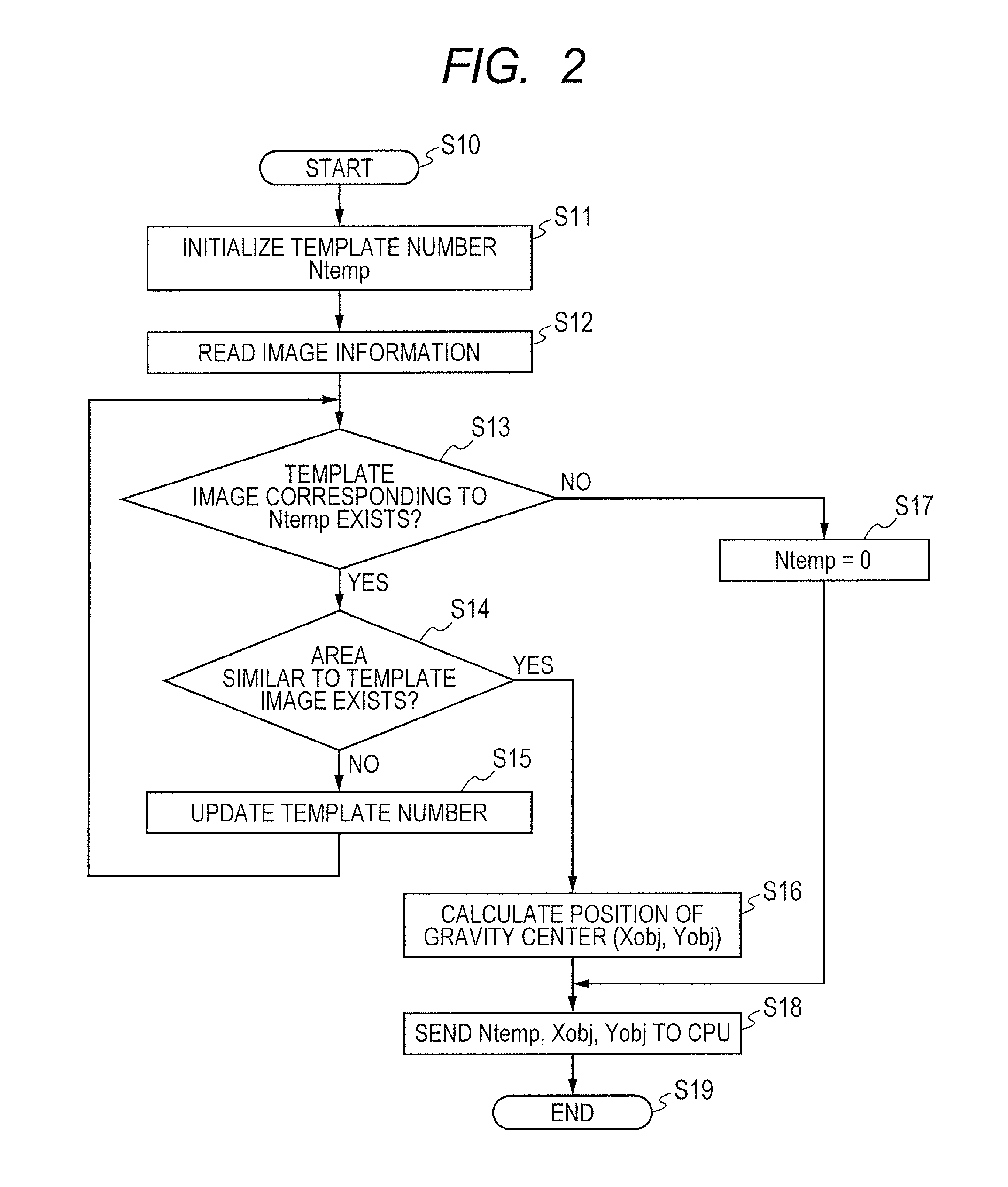
[0071]The configuration is analogous to that of Embodiment 1 illustrated in FIG. 1. The CPU 21 receives the positional. information of the current zoom, tilt and pan, from the camera platform system 30. In the memory 22, the conditional expressions uniquely determining the tracking prohibition areas for the respective template numbers Ntemp based on zoom positional information Zpt, tilt positional information and pan positional information Ppt of the current camera platform system 30 as illustrated in FIG. 15 are stored. On an object constantly moving irrespective of the pan and tilt positions, the conditional expression determines a constant tracking prohibition area irrespective of the values Tpt and Ppt. Meanwhile, on an object moving differently according to the pan and tilt positions, the conditional expression determines an appropriate tracking prohibition area according to the values Tpt and Ppt. ...


PUM


Abstract

An automatic tracking apparatus includes: an image pickup apparatus having zoom function; camera platform driving the image pickup apparatus in at least one of pan and tilt directions, and automaically tracking an object by operating the image pickup apparatus and camera platform; unit for detecting a position of the object in picked-up image information; prohibition area setting unit for setting tracking prohibition area, according to information on the automatic tracking apparatus that includes information on the object including information on at least one of type, orientation and traveling speed of the object, or information on at least one of pan and tilt positions of the camera platform and zoom position; and controller that does not perform tracking operation in the prohibition area, and performs zooming, panning and tilting to perform the tracking operation when out of the prohibition area.

Description

BACKGROUND OF THE INVENTION[0001]1. Field of the Invention[0002]The present invention relates to an automatic tracking apparatus, and particularly to an automatic tracking apparatus that automatically changes the shooting direction of a camera to automatically track a desired object.[0003]2. Description of the Related Art[0004]Conventionally, an automatic tracking apparatus has been known that performs zooming, panning and tilting of a camera platform mounted with a television camera to change the angle of view of an image acquired by the camera and the direction of the optical axis direction, thereby automatically tracking a moving object. Here, if the panning or tilting operation is performed when the object moves quiveringly within an image pickup range of the camera, an image with a shaking screen is acquired. To prevent the shake, a method has been known that provides a tracking operation prohibition area in which no tracking operation on the camera platform is performed when a...

Claims


Application Information

Patent Timeline
IPC IPC(8): H04N5/232
CPCH04N5/232H04N23/61H04N23/695
Inventor KAGEI, KENJI
Owner CANON KK
Why Eureka
Try Eureka