Optical Pickup Apparatus and Optical Disk Drive

a pickup apparatus and optical disc technology, applied in the direction of optical recording heads, instruments, data recording, etc., can solve the problems of imbalance in the tracking error signal and the interference effect, so as to reduce the fluctuation of the tracking error signal, reduce the fluctuation of the spp signal, and reduce the error in reading data

Inactive Publication Date: 2008-10-30
HITACHI MEDIA ELECTORONICS CO LTD
View PDF8 Cites 14 Cited by
  • Summary
  • Abstract
  • Description
  • Claims
  • Application Information

AI Technical Summary

Benefits of technology

[0027]In accordance with the present invention, a portion in the sub-beams where no interference with the reflected light from the adjacent layer is caused can be detected, so that the fluctuation in the SPP signal can be reduced. This makes it possible to also reduce the fluctuation in the tracking error signal formed from the SPP signal, so that the optical spot can be prevented from losing track and the error in reading data can be reduced.
[0028]When an optical disc is written with information or data, an adjacent track is also irradiated with laser light, though in small amounts. If the displacement of the laser spot from a track is large, the amount of light onto the adjacent track increases, thereby possibly erasing the data in the adjacent track. In accordance with the invention, such displacement of the laser spot from a track can be reduced, whereby the amount of light onto the adjacent track can be reduced and the adverse effect of erasing the data in the adjacent track can be reduced.

Problems solved by technology

Consequently, the effect of interference appears strongly.
If the distribution of the amount of light in the optical spot 812 or 813 is changed by the rotation of an optical disc having an uneven interlayer distance, the differential signal portion SPP=(E−F)+(G−H) of the TR signal due to the sub-beams is influenced, leading to an imbalance in the tracking error signal.
This can result in problems such as a tracking error.

Method used


Image

  • Optical Pickup Apparatus and Optical Disk Drive
  • Optical Pickup Apparatus and Optical Disk Drive
  • Optical Pickup Apparatus and Optical Disk Drive

Examples


embodiment 1

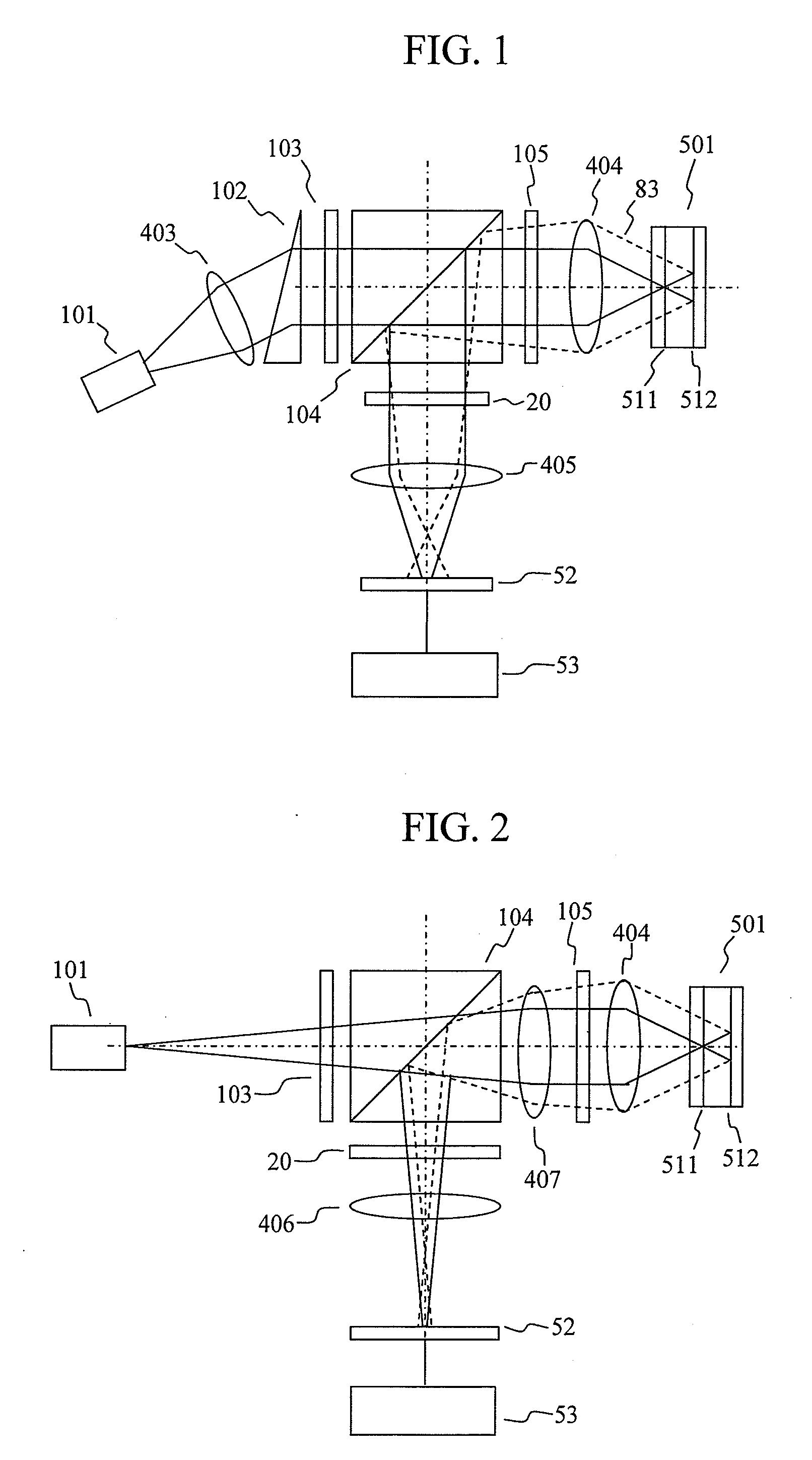
[0048]FIG. 1 shows an optical pickup apparatus for an optical disc drive. A semiconductor laser 101 emits laser light that is converted by a collimator lens 403 and a triangular prism 102 into a collimated, circular light beam. The collimated beam is divided into three beams by a diffraction grating 103; namely, one main beam and two sub-beams. While the direction of travel of the main beam is the same as the incident beam, the two sub-beams form emerging light having an inclination in symmetric directions with respect to the optical axis. Normally, the difference in the amount of light of the main beam and the sub-beams is set to be 10 times or greater. The three beams pass through a polarization beam splitter 104, converted by a quarter wavelength plate 105 into circularly polarized light, and then narrowed by an objective lens 404 onto a dual-layer optical disc 501 rotated by a rotation mechanism. In FIG. 1, the reading target layer (relevant layer) is 511, on which the minimum s...

embodiment 2

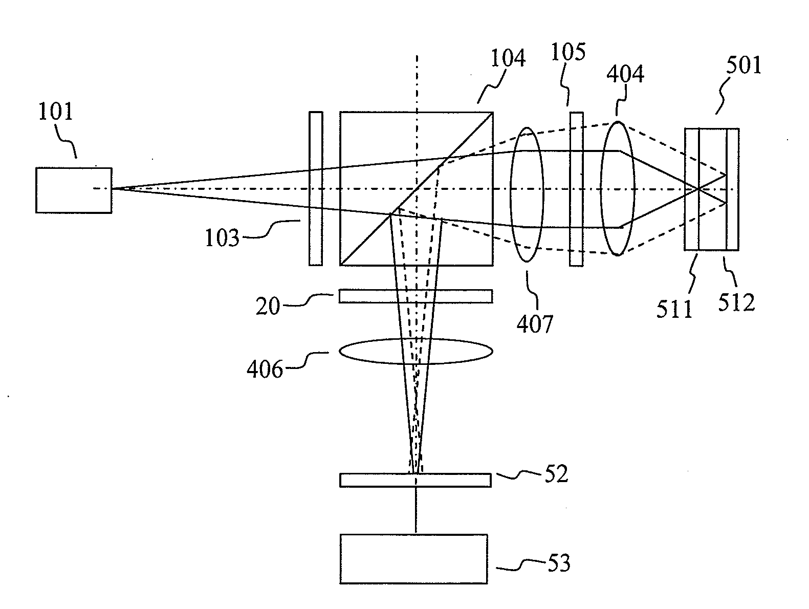
[0051]In Embodiment 2 shown in FIG. 2, the diffraction grating 103 and the polarization beam splitter 104 are disposed nearer the semiconductor laser 101 than a collimator lens 407. Thus, the laser light emitted by the semiconductor laser 101 passes through the polarization beam splitter 104 in the form of diverging light. The laser light is then converted into light beam collimated by the collimator lens 407, and then becomes incident on the quarter wavelength plate 105. The reflected light from the dual-layer optical disc 501 has its polarization direction changed by 90° and is then reflected by the polarization beam splitter 104. The reflected light passes through the split wavelength plate 20 and an astigmatism element 406, before being detected by the photodetector 52. The astigmatism element 406 may comprise a cylindrical lens. In the present embodiment, a number of components are disposed between the laser light source 101 and the collimator lens 407 with the polarization bea...

embodiment 3

[0052]In Embodiment 3, a split wavelength plate shown in FIG. 10 is used. The split wavelength plate 21 is inserted in the optical path in place of the split wavelength plate 20 of Embodiment 1. The region of influence of interference from the adjacent layer due to the sub-beams differs from that in the case of the split wavelength plate 20, as mentioned above. Assuming that four-quadrant photodetectors 541, 544, and 545 having the same configuration are used, the inputs from the four-quadrant detectors 544 and 545 into the electronic circuit 52 need to be changed.

[0053]FIG. 13 shows a signal processing circuit configured such that the push-pull signals for the sub-beams are formed by a diagonal combination of the four-quadrant detectors. When the relevant layer is changed, a push-pull signal from a diagonal combination having less influence from the adjacent layer is selected by a switch element 580, which is controlled by a layer selection control circuit 727. While the circuits o...


PUM

PropertyMeasurementUnit
wavelengthsaaaaaaaaaa
angleaaaaaaaaaa
widthaaaaaaaaaa

Abstract

When tracking a dual-layer optical disc by a differential push-pull method, the adverse effect of the reflected light from an adjacent layer, which produces stray light, on a tracking control signal is prevented. A split wavelength plate 20 is inserted in the optical path of the reflected light from the optical disc including the stray light from the adjacent layer so as to detect a region having no interference with the stray light with a four-quadrant detector, and then a push-pull signal by a sub-beam is formed.

Description

CLAIM OF PRIORITY[0001]The present application claims priority from Japanese application JP2007-119044 filed on Apr. 27, 2007, the content of which is hereby incorporated by reference into this application.BACKGROUND OF THE INVENTION[0002]1. Field of the Invention[0003]The present invention relates to optical pickup apparatuses and optical disc drives, and particularly to an optical pickup apparatus and an optical disc drive having features in their reading optical systems.[0004]2. Background Art[0005]The capacity of an individual layer of an optical disc greatly depends on the wavelength of the semiconductor laser used and the numerical aperture (NA) of the objective lens. Specifically, the shorter the wavelength of the semiconductor laser, or the greater the NA, the greater the recording density can be made, with the resultant increase in the capacity per layer. Most of the currently commercially available optical disc drives are the DVD (Digital Versatile Disc) drives that employ...

Claims


Application Information

Patent Timeline
Patent Type & Authority Applications(United States)
IPC IPC(8): G11B21/08
CPCG11B7/0903G11B7/0909G11B7/131G11B7/1365G11B7/1381G11B2007/0013
Inventor KIMURA, SHIGEHARUSHIMANO, TAKESHI
Owner HITACHI MEDIA ELECTORONICS CO LTD
Why Eureka
Try Eureka