Optical scanner and image forming apparatus

a technology which is applied in the field of optical scanner and image forming apparatus, can solve the problems of difficult to sufficiently suppress stiff support frame, etc., and achieve the effect of suppressing the light reflecting plate from being bent and stiff support fram

Active Publication Date: 2013-10-24
SEIKO EPSON CORP
View PDF5 Cites 17 Cited by
  • Summary
  • Abstract
  • Description
  • Claims
  • Application Information

AI Technical Summary

Benefits of technology

[0008]An advantage of some aspects of the invention is to provide an optical scanner and an image forming apparatus that are capable of sufficiently suppressing a light reflecting plate from being bent.

Problems solved by technology

In the optical scanner disclosed in US-A-2011-249020, since the thickness of the light reflecting plate and the thickness of the support frame is the same, the stiffness of the support frame is insufficient, and it is thus difficult to sufficiently suppress the light reflecting plate from being bent.

Method used


Image

  • Optical scanner and image forming apparatus
  • Optical scanner and image forming apparatus
  • Optical scanner and image forming apparatus

Examples


first embodiment

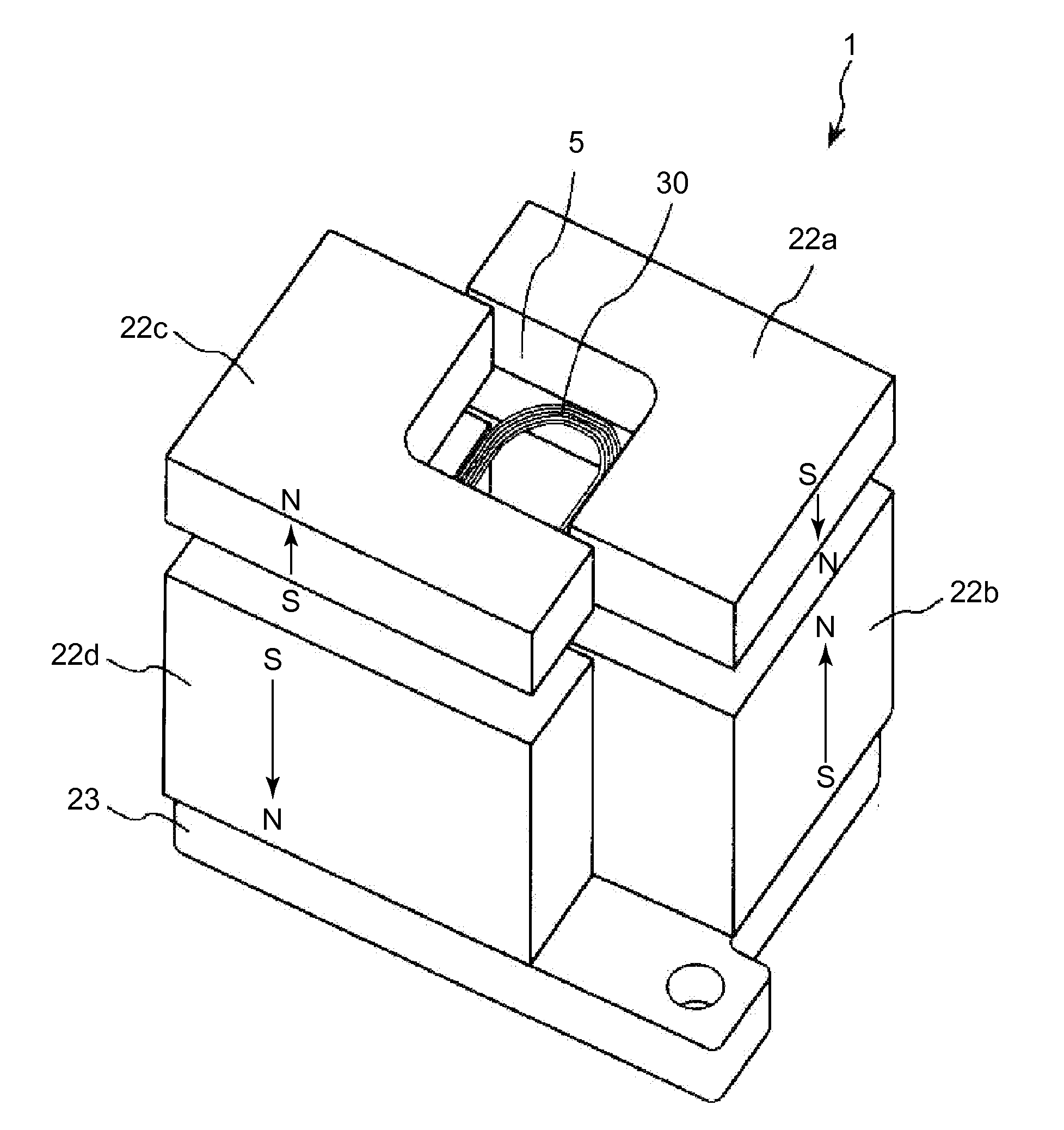
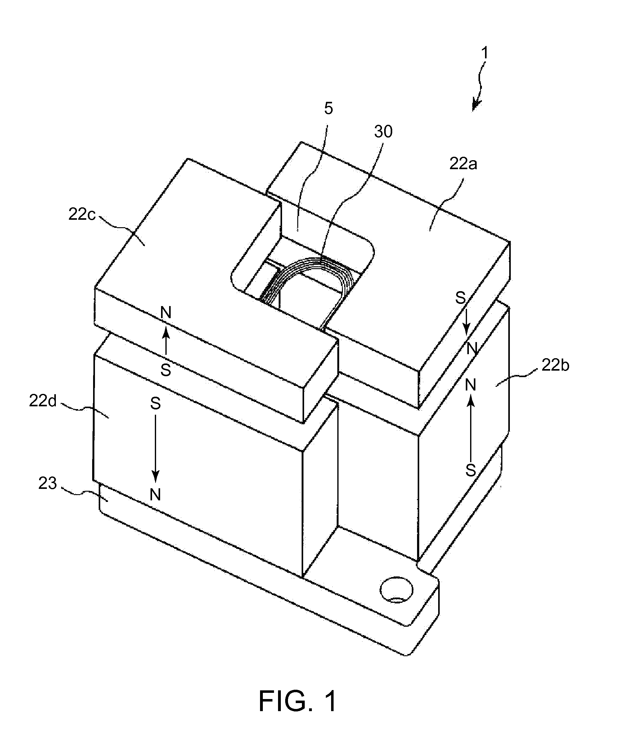
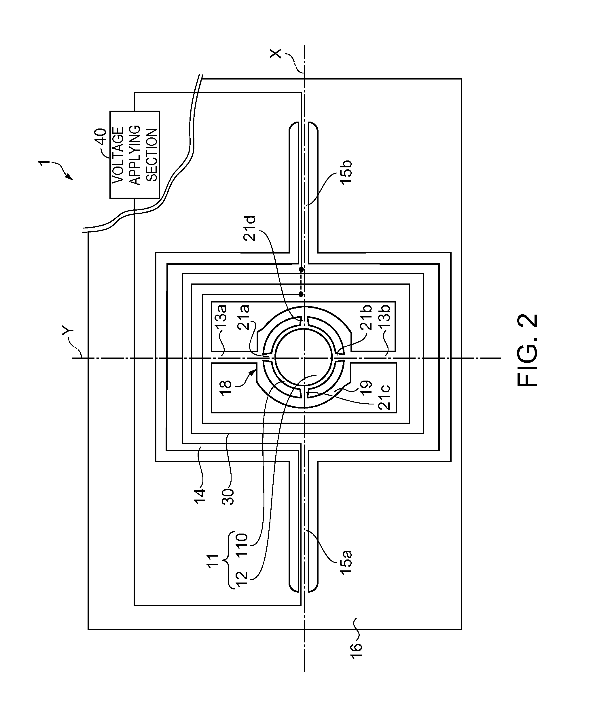
[0045]FIG. 1 is a perspective view illustrating a first embodiment of an optical scanner according to the invention, FIG. 2 is a plan view illustrating a movable section, each shaft member, a frame-shaped member, a coil and the like of the optical scanner shown in FIG. 1, FIG. 3 is a cross-sectional view illustrating the movable section of the optical scanner shown in FIG. 1, FIG. 4 is a block diagram illustrating a voltage applying section of a drive unit provided in the optical scanner shown in FIG. 1, FIGS. 5A and 5B are diagrams illustrating an example of voltage generated in a first voltage generating section and a second voltage generating section shown in FIG. 4. Hereinafter, for ease of description, an upper side in FIGS. 1 and 3 is referred to as “up”, a lower side therein is referred to as “down”, a right side therein is referred to as “right”, and a left side therein is referred to as “left”. Further, a front side on the plane in FIG. 2 is referred to as “up”, a rear side...

second embodiment

[0097]FIG. 6 is a plan view illustrating a movable section, each shaft member, a coil and the like in a second embodiment of an optical scanner according to the invention. Hereinafter, for ease of description, a front side on the plane in FIG. 6 is referred to as “up”, a rear side thereon is referred to as “down”, a right side thereon is referred to as “right”, and a left side thereon is referred to as “left”.

[0098]Hereinafter, in the second embodiment, different points from the above-described first embodiment will be mainly described, and the same configuration will not be described.

[0099]As shown in FIG. 6, an optical scanner 1 according to the second embodiment includes a substrate 23, a movable section 18, a pair of shaft members (first shaft members) 13a and 13b, a support member 16, four permanent magnets 22a, 22b, 22c and 22d, a coil 30 that generates a magnetic field by application of voltage, and a voltage applying section 40 that applies voltage to the coil 30 (see FIG. 1...

third embodiment

[0107]FIG. 7 is a plan view illustrating a third embodiment of an optical scanner according to the invention, and FIG. 8 is a cross-sectional view taken along line A-A in FIG. 7.

[0108]Hereinafter, for ease of description, a front side on the plane in FIG. 7 is referred to as “up”, a rear side thereon is referred to as “down”, a right side thereon is referred to as “right”, and a left side thereon is referred to as “left”. An upper side in FIG. 8 is referred to as “up”, a lower side therein is referred to as “down”, a right side therein is referred to as “right”, and a left side therein is referred to as “left”.

[0109]Hereinafter, with respect to the third embodiment, different points from the above-described first embodiment will be mainly described, and the same configuration will not be described.

[0110]As shown in FIGS. 7 and 8, an optical scanner 1 according to the third embodiment includes a movable section 18, a pair of shaft members (second shaft members) 13a and 13b, a frame-s...


PUM


Abstract

An optical scanner includes: a movable body that is able to oscillate around a first axis; a first shaft member that is connected to the movable body along the first axis; and a drive unit that includes a permanent magnet, a coil that generates a magnetic field by application of voltage, and a voltage applying section that applies a voltage to the coil and oscillates the movable body around the first axis, wherein the movable body includes a light reflecting plate provided with a light reflecting section having light reflectivity, a support frame that surrounds the light reflecting plate and has a thickness that is, ten times or less, larger than the thickness of the light reflecting plate, and a plurality of connecting sections that connects the light reflecting plate and the support frame at a plurality of locations.

Description

BACKGROUND[0001]1. Technical Field[0002]The present invention relates to an optical scanner and an image forming apparatus.[0003]2. Related Art[0004]For example, US-A-2011-249020 discloses an optical scanner that two-dimensionally scans light, as an optical scanner for performing image drawing by light scanning in a projector, a printer or the like.[0005]The optical scanner disclosed in US-A-2011-249020 includes a frame-shaped member that is able to oscillate around a first axis, a movable section that is provided inside the frame-shaped member and is able to oscillate around a second axis perpendicular to the first axis, a permanent magnet, and a coil. Further, the movable section includes a light reflecting plate provided with a light reflecting section having light reflectivity, a support frame that surrounds the light reflecting plate, and a plurality of connecting sections that connects the light reflecting plate and the support frame at a plurality of locations. The coil is di...

Claims


Application Information

Patent Timeline
Patent Type & Authority Applications(United States)
IPC IPC(8): G02B26/10
CPCG02B26/105G02B26/085G02B26/101G02B27/104
Inventor HINO, MAKIKOMIZOGUCHI, YASUSHI
Owner SEIKO EPSON CORP
Why Eureka
Try Eureka