
Imaging device provided with lens having moth-eye structure

a technology of moth-eye structure and imaging device, which is applied in the field of imaging device, can solve the problems of insufficient suppression of reflection, insufficient ghosting and flare, and the effect of reducing image quality

Inactive Publication Date: 2018-05-10
DENSO CORP
View PDF16 Cites 3 Cited by
  • Summary
  • Abstract
  • Description
  • Claims
  • Application Information

AI Technical Summary

Benefits of technology

This patent describes a technique that improves the quality of captured images by reducing ghost and flares. It uses a moth-eye structure to suppress light reflection on the surface of a transparent member, resulting in improved image quality. The configuration helps to reduce image quality degradation caused by light reflections and other optical effects.

Problems solved by technology

However, an anti-reflection coating is not sufficient to suppress the reflection so that ghosting and flare are sufficiently reduced.
Therefore, a problem arises that image quality is likely to decrease.

Method used


Image

  • Imaging device provided with lens having moth-eye structure
  • Imaging device provided with lens having moth-eye structure
  • Imaging device provided with lens having moth-eye structure

Examples


embodiment

1. Embodiment

1-1. Overall Configuration

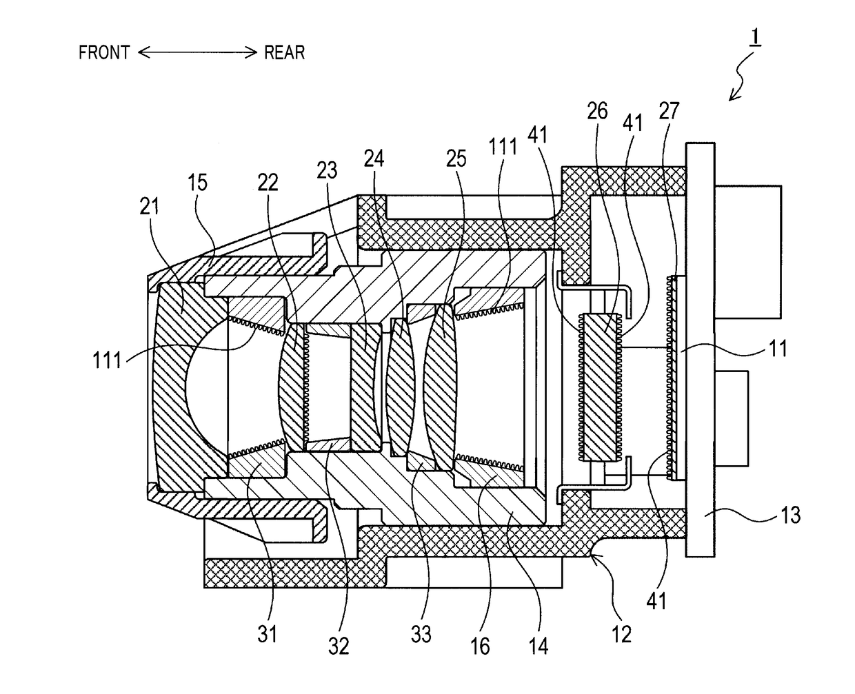
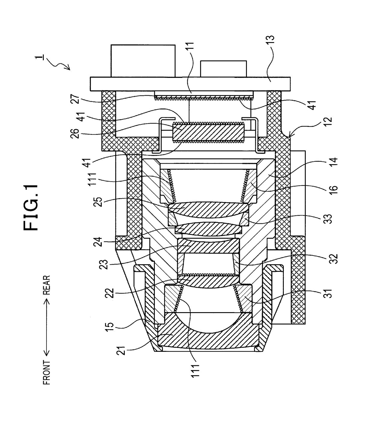
[0021]An imaging device 1 shown in FIG. 1 is used as being mounted on vehicles such as cars and railroad vehicles. In the following description, a front direction is defined as a direction where the object exists with respect to the imaging device 1, and a rear direction is defined as a direction where the imaging device 1 exists with respect to the object. These front and rear directions are used for convenience only, and do not limit usage or configuration of the imaging device 1.

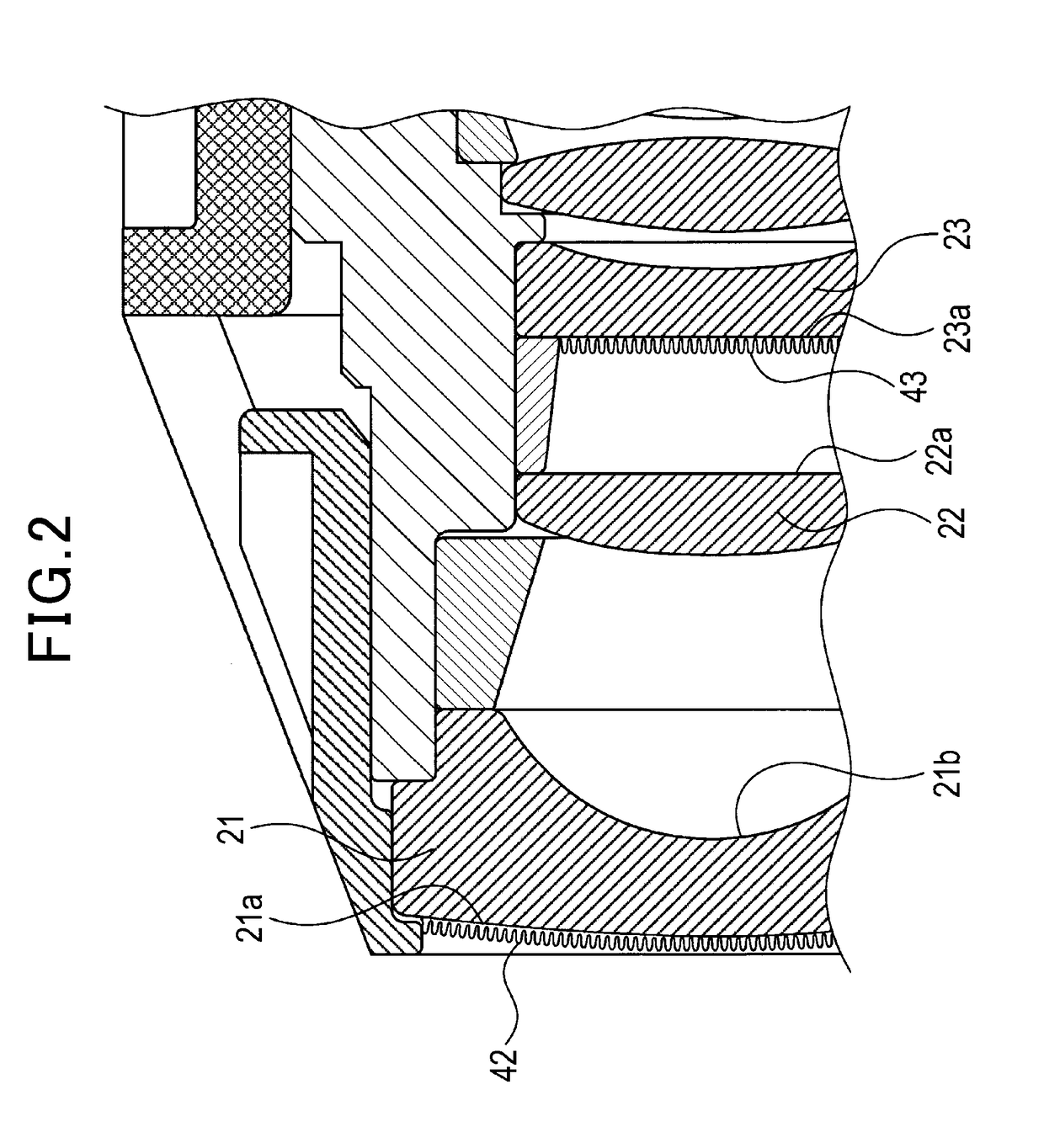
[0022]The imaging device 1 is provided with an imaging element 11, a first lens 21, a second lens 22, a third lens 23, a fourth lens 24, a fifth lens 25, an IR cut filter 26, and a cover glass 27. Also, the imaging device 1 includes a first gap ring 31, a second gap ring 32, a third gap ring 33, a retainer 16 and a housing 12. The imaging element 11 is configured to capture an object and output an image signal showing an image of the object. The first lens 21, the se...


PUM


Abstract

An imaging device mounted on a vehicle is provided. The imaging device includes an imaging element, a plurality of transparent members and a housing. The imaging element is configured to capture an object and output an image signal of the object. The plurality of transparent members includes at least one lens, and is arranged on a light transmission path of light that reaches the imaging element. The housing is configured to hold the imaging element and the plurality of transparent members. Moreover, the imaging device is provided with a moth-eye structure arranged on at least one surface among the plurality of transparent members.

Description

CROSS-REFERENCE TO RELATED APPLICATION[0001]This application is based on and claims the benefit of priority from earlier Japanese Patent Application No. 2016-218058 filed Nov. 8, 2016, the description of which is incorporated herein by reference.BACKGROUNDTechnical Field[0002]The present disclosure relates to an imaging device that captures an object. More particularly, the present disclosure relates to an imaging device provided with a lens having a moth-eye structure.Description of the Related Art[0003]According to an imaging device using a plurality of lenses, it is required to reduce ghost and flare which may occur due to light reflection between lenses, in order to improve quality of captured images. In this respect, JP-A-2005-301172 discloses a technique in which a low reflection coating is applied to lenses.[0004]However, an anti-reflection coating is not sufficient to suppress the reflection so that ghosting and flare are sufficiently reduced. In the case where the imaging d...

Claims


Application Information

Patent Timeline
IPC IPC(8): G02B1/118G02B27/00G02B7/02H04N5/225
CPCG02B1/118G02B27/0018G02B7/021H04N5/2257H04N23/55H04N23/57
Inventor HIBINO, KATSUHIKOTAKAMA, DAISUKE
Owner DENSO CORP
Learn More