Assembly of a part that has no plastic domain

a technology of plastic domains and parts, applied in the field of parts assembly, can solve the problem of extremely delicate application of operations

Active Publication Date: 2013-10-31
ETA SA MFG HORLOGERE SUISSE
View PDF10 Cites 16 Cited by
  • Summary
  • Abstract
  • Description
  • Claims
  • Application Information

AI Technical Summary

Benefits of technology

[0003]It is an object of the present invention to overcome all or part of the aforecited drawbacks by providing an adhesive-free assembly which can secure a part made of a material with no plastic domain to a member comprising a ductile material, such as, for example, a metal or metal alloy.
[0005]This configuration advantageously enables the unit comprising the part-member to be secured without bonding to an ordinary, precision controlled member, while ensuring that the part is not subject to destructive stresses, even if is is formed, for example, from silicon.
[0022]This method advantageously allows the member to be radially secured without any axial stress being applied to the part. Indeed, advantageously according to the invention, only radial, elastic deformation is applied to the part. Finally, this method unites the assembly comprising the part-member by adapting to the dispersions in manufacture of the various components.

Problems solved by technology

This type of operation requires extremely delicate application which makes it expensive.

Method used


Image

  • Assembly of a part that has no plastic domain
  • Assembly of a part that has no plastic domain
  • Assembly of a part that has no plastic domain

Examples


first embodiment

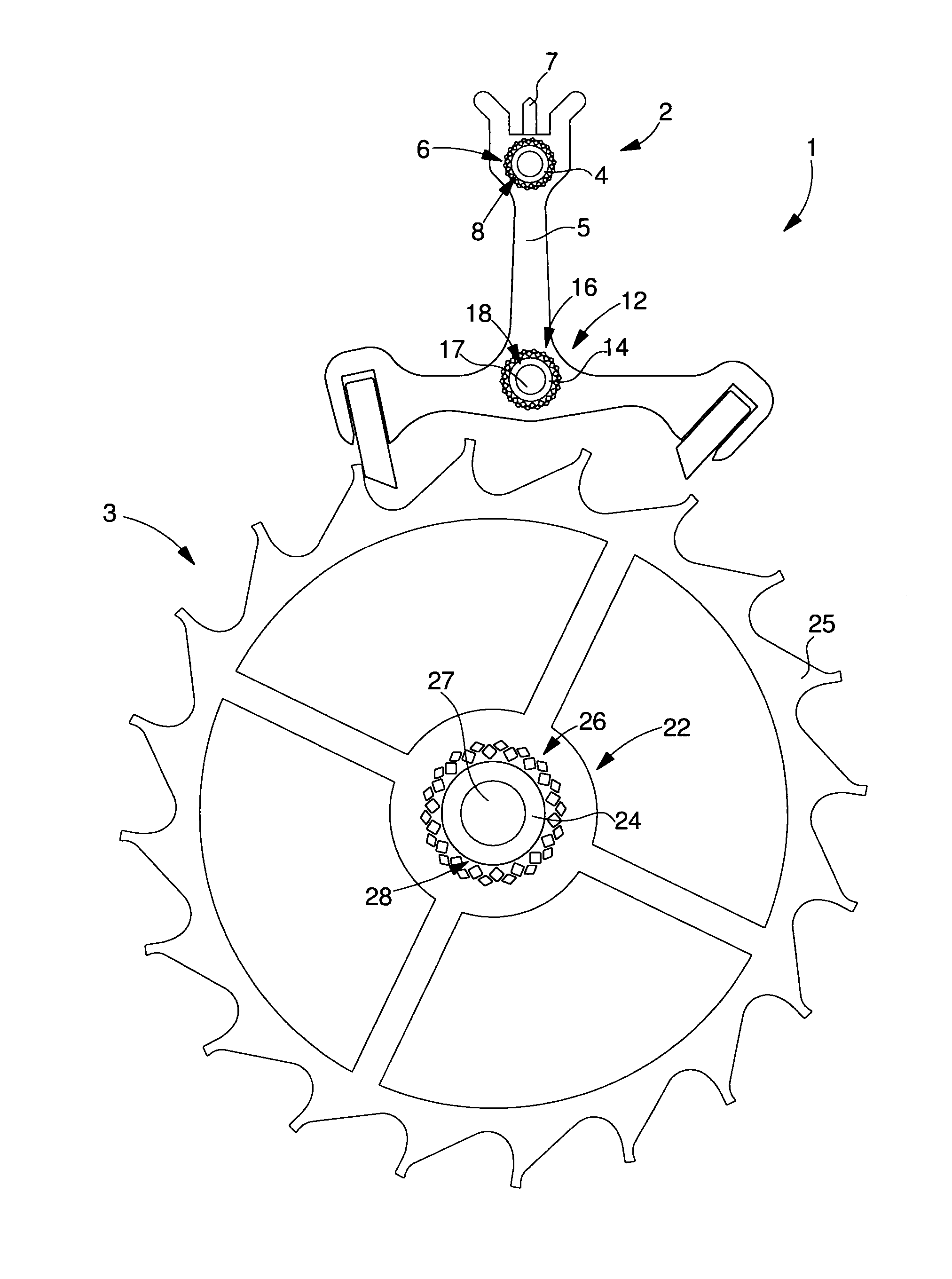
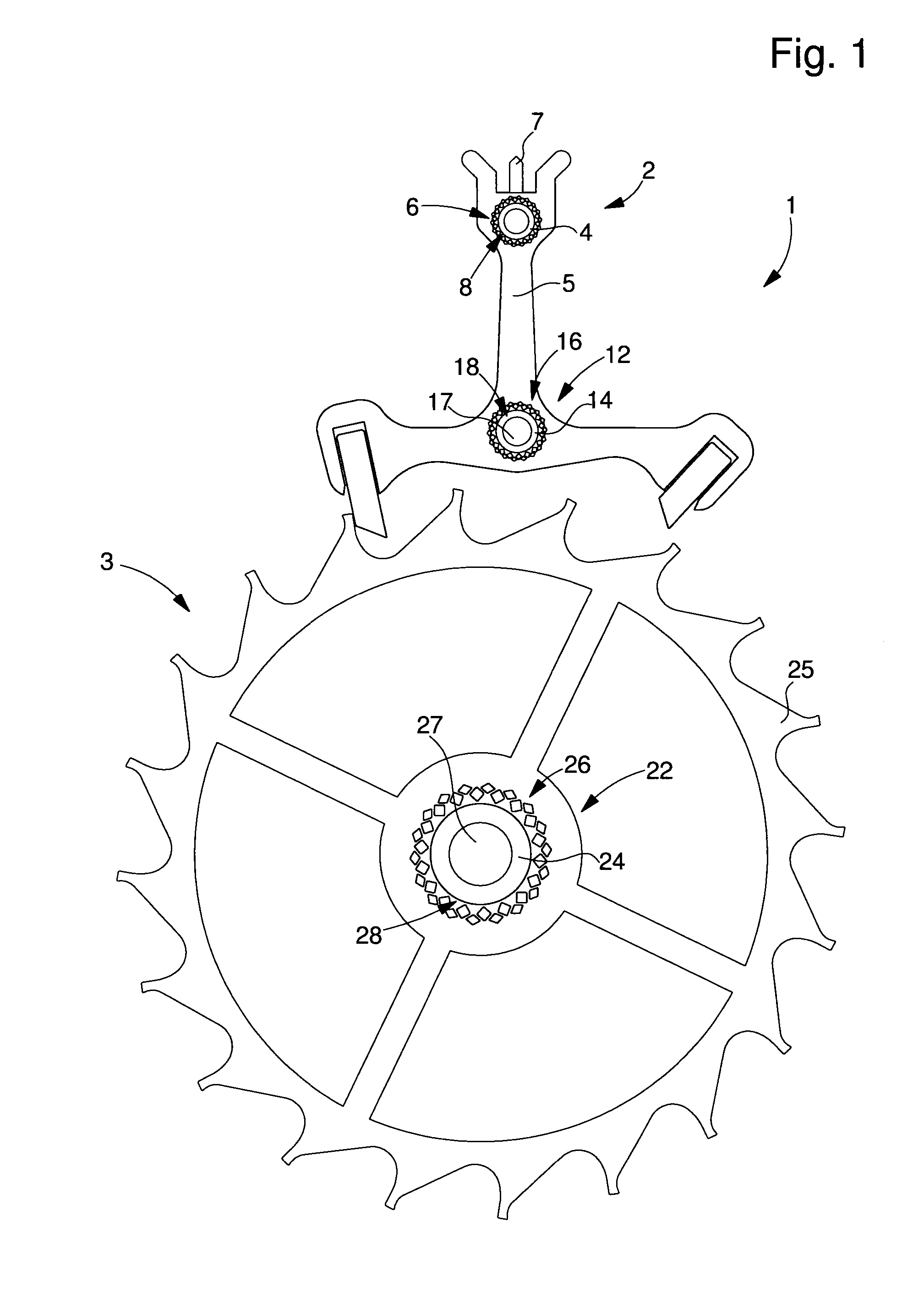
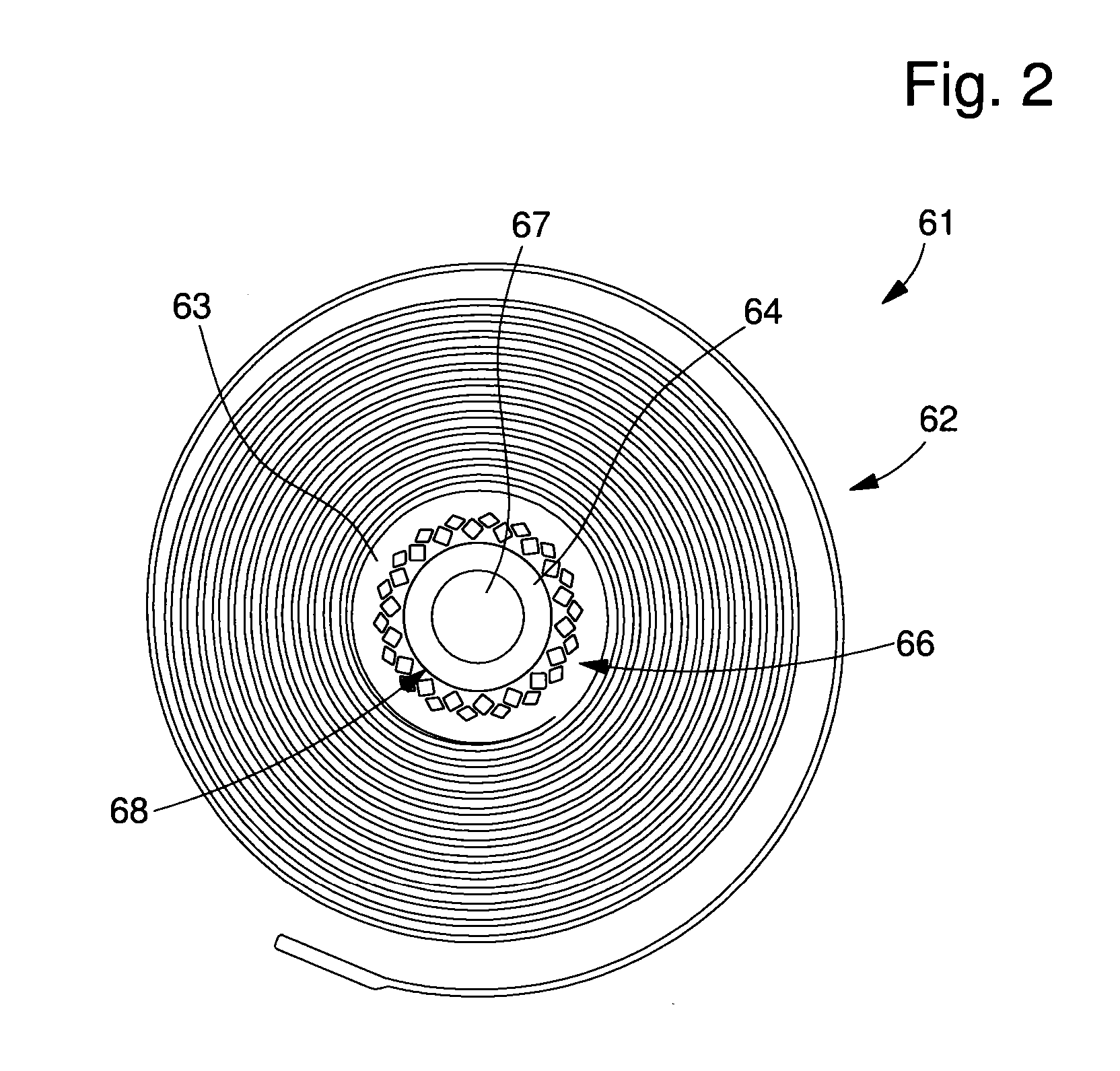
[0056]Examples of pierced holes are shown in FIGS. 3 to 8. illustrated in FIGS. 3 to 6, the pierced holes are formed at a distance from and around the aperture by two series of diamond-shaped holes distributed in a quincunx arrangement so as to form beams arranged in secant V-shapes.

[0057]FIG. 3 is a diagram of pierced holes 6, 16, 26, 66 of FIGS. 1 and 2. For more simplicity, only the wheel 3 references are used again in FIG. 3. FIG. 3 shows pierced holes 26, which preferably pass through the entire thickness of body 25, made of fragile material. Pierced holes 26 are distributed at a distance from and around aperture 28 which is also preferably formed to pass through the entire thickness of body 25 made of fragile material.

[0058]As seen in FIG. 3, pierced holes 26 form a first series of holes 31, the farthest from aperture 28, and a second series of holes 33, which are diamond-shaped and in a quincunx arrangement. FIG. 3 shows that pierced holes 31, 33 thus form V-shaped beams 32 ...

second embodiment

[0065] illustrated in FIGS. 7 and 8, the pierced holes are formed at a distance from and around the aperture by a first series of oblong holes distributed in a quincunx arrangement with a second series of triangular holes, the second series being closest to the circular aperture, each triangular hole communicating with the aperture via a notch so as to form beams that are radially moveable according to the thickness of the oblong holes.

[0066]Thus, FIG. 7 shows pierced holes 46 which preferably pass through the entire thickness of body 25, made of fragile material. Pierced holes 46 are distributed at a distance from and around aperture 28 which is also preferably formed to pass through the entire thickness of body 25 made of fragile material.

[0067]As seen in FIG. 7, pierced holes 46 form a first series of oblong holes 51 and a second series of triangular holes 53. According to the second embodiment, the two series of holes 51, 53 are arranged in a quincunx arrangement.

[0068]Further, ...


PUM

PropertyMeasurementUnit
widthaaaaaaaaaa
widthaaaaaaaaaa
displacementaaaaaaaaaa

Abstract

An assembly of an axially extending member, made of a first material, in an aperture of a part, made of a second material having no plastic domain. The part includes pierced holes forming an elastic deformation mechanism distributed around the aperture thereof. Further, the member includes an elastically and plastically deformed, radially flared portion that radially grips a wall of the part surrounding the aperture by stressing the elastic deformation mechanism, so as to secure the assembly in a manner that is not destructive for the part. The assembly can be used in the field of timepieces.

Description

FIELD OF THE INVENTION[0001]The invention relates to the assembly of a part, made of a material having no plastic domain, to a member comprising a different type of material.BACKGROUND OF THE INVENTION[0002]Current assemblies including a silicon-based part are generally secured by bonding. This type of operation requires extremely delicate application which makes it expensive.SUMMARY OF THE INVENTION[0003]It is an object of the present invention to overcome all or part of the aforecited drawbacks by providing an adhesive-free assembly which can secure a part made of a material with no plastic domain to a member comprising a ductile material, such as, for example, a metal or metal alloy.[0004]The invention therefore relates to an assembly of an axially extending member, made of a first material, in the aperture of a part made of a second material having no plastic domain, characterized in that the part includes pierced holes forming elastic deformation means distributed around the ap...

Claims


Application Information

Patent Timeline
Patent Type & Authority Applications(United States)
IPC IPC(8): G04B13/02G04B17/32G04B1/14G04B15/14
CPCG04B13/02G04B15/14G04B17/32G04B1/145G04B13/026G04B13/022G04B17/325G04B17/345G04D1/0042G04D3/04G04B13/021Y10T29/49581
Inventor CONUS, THIERRYVERARDO, MARCOSAGLINI, IGORKOHLER, FREDERIC
Owner ETA SA MFG HORLOGERE SUISSE
Why Eureka
Try Eureka