Device for connecting or filling and method

a technology of connecting or filling devices and connectors, applied in the direction of couplings, packaging goods types, transportation and packaging, etc., can solve the problems of interior of the cannula or probe, can be exposed to the ambient atmosphere, and typical controlled environments

Inactive Publication Date: 2013-11-07
INTACT CLOSED TRANSFER CONNECTORS LLC
View PDF24 Cites 36 Cited by
  • Summary
  • Abstract
  • Description
  • Claims
  • Application Information

AI Technical Summary

Benefits of technology

[0054]One advantage of the present invention is that it provides a closed system sterile transfer, such that product transferred within the system does not come in contact with the external environment or contaminants therefrom. Another advantage of the present inventions is that the filling device and the connector can aseptically fill and transfer fluid within a non-aseptic, non-sterile or relatively low SAL environment (e.g., about log 6 or lower). Other objects and advantages of the present invention, and / or of the currently preferred embodiments thereof, will become more readily apparent in view of the following detailed description and the accompanying drawings.

Problems solved by technology

One drawback encountered with previously-known filling cannulas and needles is that the interior of the cannula or probe, and any fluid contained therein or passing therethrough, can be exposed to the ambient atmosphere via the open fluid ports.
However, typical controlled environments, such as a class 100 (ISO-5) controlled environment, are not truly sterile.
Although the likelihood of contamination in such reduced-contaminant environments may be relatively low, just one colony of contaminants can develop into a container full of germs over its shelf-life.
This risk is exacerbated when filling traditional open containers that are thereafter sealed in an assembly machine.
No such previously-known assembly machine, such as, for example, a typical machine closing 40,000 containers per hour, can fully prevent entrance of viables and non-viables into the containers.
On the other hand, if the cannula or probe is used to dispense a contaminated fluid, or a fluid that might be harmful if it is exposed to or comes into contact with an operator, the open ports can allow such fluid to contaminate its ambient atmosphere or potentially harm the operator that contacts the cannula or probe or is in the vicinity thereof.
Such fluid connectors typically do not prevent the contamination of fluids passing through them, unless the connector is sterile handled and connected in a relatively low challenging environment (even then, the connectors must be sealingly connected to each other to prevent ingress of contaminants, which means the connection cannot be disengaged).
For example, prior to interconnection of the male and female connectors, the fluid-contacting surfaces thereof can be exposed to the ambient atmosphere and contaminated through contact with airborne germs and / or by contact with contaminated surfaces.
One drawback of this approach is that the fluid-contacting surfaces may become contaminated after the wipe is applied to the male and female connectors.
Another drawback of this approach is that it can be time consuming and considered a nuisance, and therefore unreliable in practice.
There is no previously-known connector capable connection within a contaminated liquid or contaminated aerosol chamber that prevents the contamination of fluids passing therethrough.
Accordingly, aseptic or sterile fluids can be subjected to contamination when passed through such previously-known connectors.
According to the Center for Disease Control (CDC), approximately 200,000 cases CRBSI are reported in the United States per year and cost the country about $35 billion in treatment costs.
CRBSI leads to about 30,000 deaths per year in United States hospitals.
If the fluids are contaminated upon passage through a fluid connector, this can lead to contamination of previously-sterile food products, and if such contaminated products are ingested, they can cause infections and / or illnesses.
If the fluid-contacting surfaces of the connector are exposed to human contact, or surfaces that come into human contact, for example, this can lead to possible injury and / or illnesses.
For example, operators exposed to the transfer of liquids such as immune suppressants or hormones, can suffer from pulmonary absorption of such products.

Method used


Image

  • Device for connecting or filling and method
  • Device for connecting or filling and method
  • Device for connecting or filling and method

Examples


Embodiment Construction

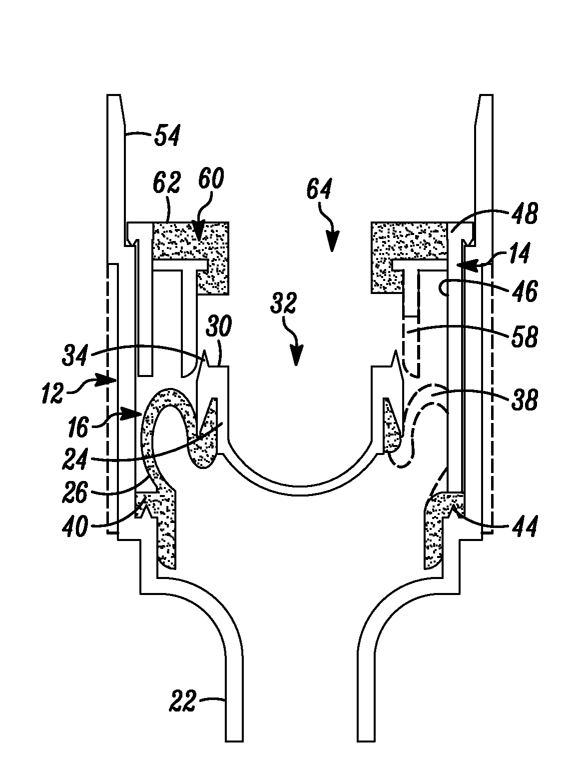
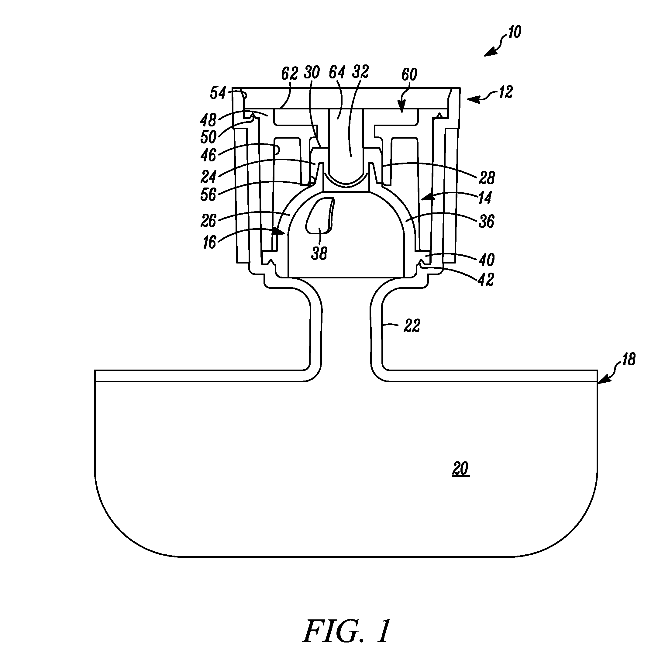
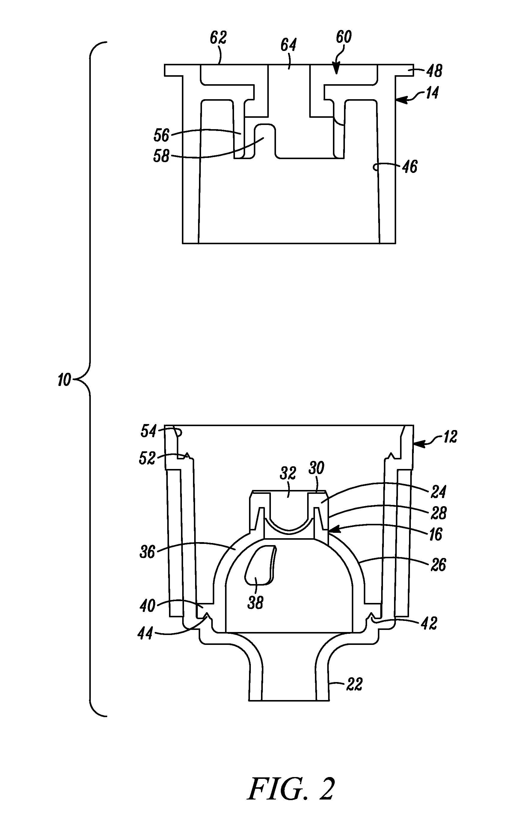
[0069]In FIG. 1 a valve is indicated generally by the reference numeral 10. The valve 10 comprises a shell 12, a flexible valve member 16 sealingly mounted within the shell 12 and a valve body 14 mounted atop the flexible valve member 16 within the shell 12, as explained further below. In some embodiments, the shell 12 is made of a polymeric or thermoplastic material such as polypropylene (PP) or high-density polyethylene (HDPE). However, as may be recognized by those of ordinary skill in the pertinent art based on the teachings herein, the shell may be made of any of numerous different materials that are currently known or that later become known. The valve 10 is connected, at a bottom end thereof, in fluid communication with a container 18, defining a storage chamber 20 therein, via a neck 22. In the illustrated embodiment, the container 18 is a pouch. However, as may be recognized by those of ordinary skill in the pertinent art based on the teachings herein, the container may def...


PUM

PropertyMeasurementUnit
flexibleaaaaaaaaaa
elasticaaaaaaaaaa
thicknessaaaaaaaaaa

Abstract

A valve comprises a shell, a flexible valve member sealingly mounted within the shell, and a valve body mounted atop the flexible valve member within the shell. The flexible member is moveable between closed and open positions to allow the flow of fluid therethrough. The valve is engageable with a filling device having flow ports and a surrounding closure. The closure and/or the shaft is movable between (i) a first position wherein the closure closes the port(s), and (ii) a second position opening the port(s). Alternatively, the valve may comprise a portion of a female connector and the filling device may comprise a portion of a male connector to form an aseptic fluid connector for the aseptic transfer of fluid therethrough.

Description

CROSS-REFERENCE TO RELATED APPLICATIONS[0001]This patent application claims benefit under 35 U.S.C. §119 to similarly-titled U.S. Provisional Patent Application No. 61 / 641,248, filed May 1, 2012, and 61 / 794,255, filed Mar. 15, 2013, both of which are hereby incorporated by reference in their entirety as part of the present disclosure.FIELD OF THE INVENTION[0002]The present invention relates to filling devices and connectors, and methods of filling and transferring fluids, and more particularly to methods of aseptically filling devices and connectors for the aseptic filling and transfer of fluids.BACKGROUND[0003]A typical previously-known filling cannula or probe used for aseptic or so called “sterile” filling comprises a hollow filling tube including an outlet port in fluid communication between the hollow interior of the filling tube and ambient atmosphere. A previously-known filling cannula or probe, for example, includes a hollow stainless steel shaft, a bulbous tip fixedly secur...

Claims


Application Information

Patent Timeline
Patent Type & Authority Applications(United States)
IPC IPC(8): F16L29/02
CPCF16L29/02A61M39/26B65B3/003B65B39/001A61M2039/268A61M39/18
Inventor PY, DANIEL
Owner INTACT CLOSED TRANSFER CONNECTORS LLC
Why Eureka
Try Eureka