
Method and apparatus for transmitting and receiving signals

a technology of applied in the field of method and apparatus for transmitting and receiving signals, can solve the problems of deteriorating system performance and lower spectrum efficiency than amplitude modulation, and achieve the effect of improving spectrum efficiency

Inactive Publication Date: 2013-11-07
ELECTRONICS & TELECOMM RES INST
View PDF19 Cites 0 Cited by
  • Summary
  • Abstract
  • Description
  • Claims
  • Application Information

AI Technical Summary

Benefits of technology

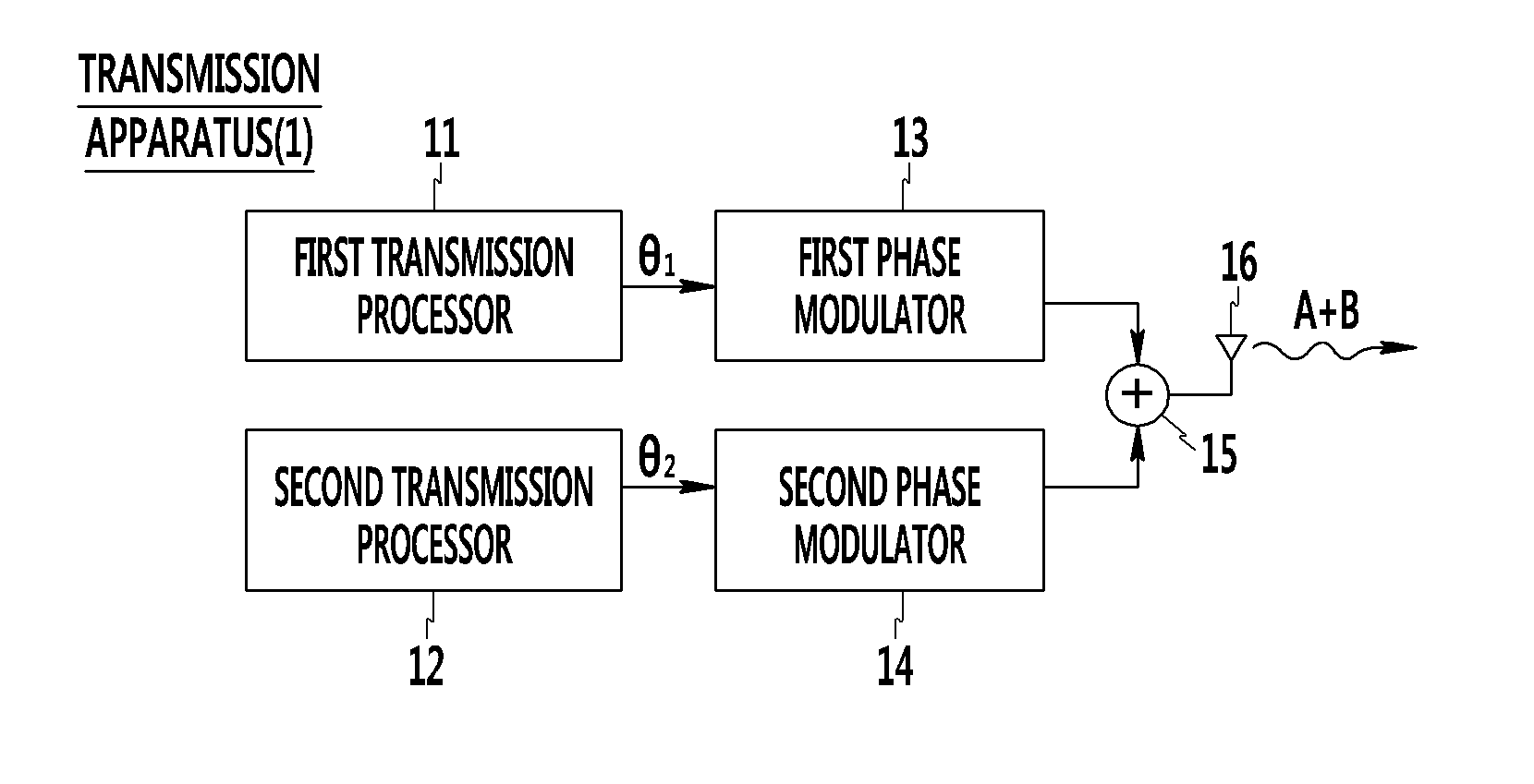
The invention provides a way to send and receive signals using phase modulation with improved spectrum efficiency. This means that the method and device make better use of the available spectrum for transmitting and receiving signals.

Problems solved by technology

If sufficient back-off for power is not given, the frequency spectrum of a system is widened and distortion due to modulation between frequencies is generated, thereby deteriorating system performance.
As described above, the phase modulation can provide service using the low output of a transmitter owing to a better noise characteristic and a lower PAPR than the amplitude modulation, but has lower spectrum efficiency than the amplitude modulation.

Method used


Image

  • Method and apparatus for transmitting and receiving signals
  • Method and apparatus for transmitting and receiving signals
  • Method and apparatus for transmitting and receiving signals

Examples


Embodiment Construction

[0027]In the following detailed description, only certain exemplary embodiments of the present invention have been shown and described, simply by way of illustration. As those skilled in the art would realize, the described embodiments may be modified in various different ways, all without departing from the spirit or scope of the present invention. Accordingly, the drawings and description are to be regarded as illustrative in nature and not restrictive. Like reference numerals designate like elements throughout the specification.

[0028]In the entire specification, unless explicitly described to the contrary, the word “comprise” and variations, such as “comprises” or “comprising”, will be understood to imply the inclusion of stated elements but not the exclusion of any other elements.

[0029]Hereinafter, a method and apparatus for transmitting and receiving signals in accordance with exemplary embodiments of the present invention are described with reference to the accompanying drawin...


PUM


Abstract

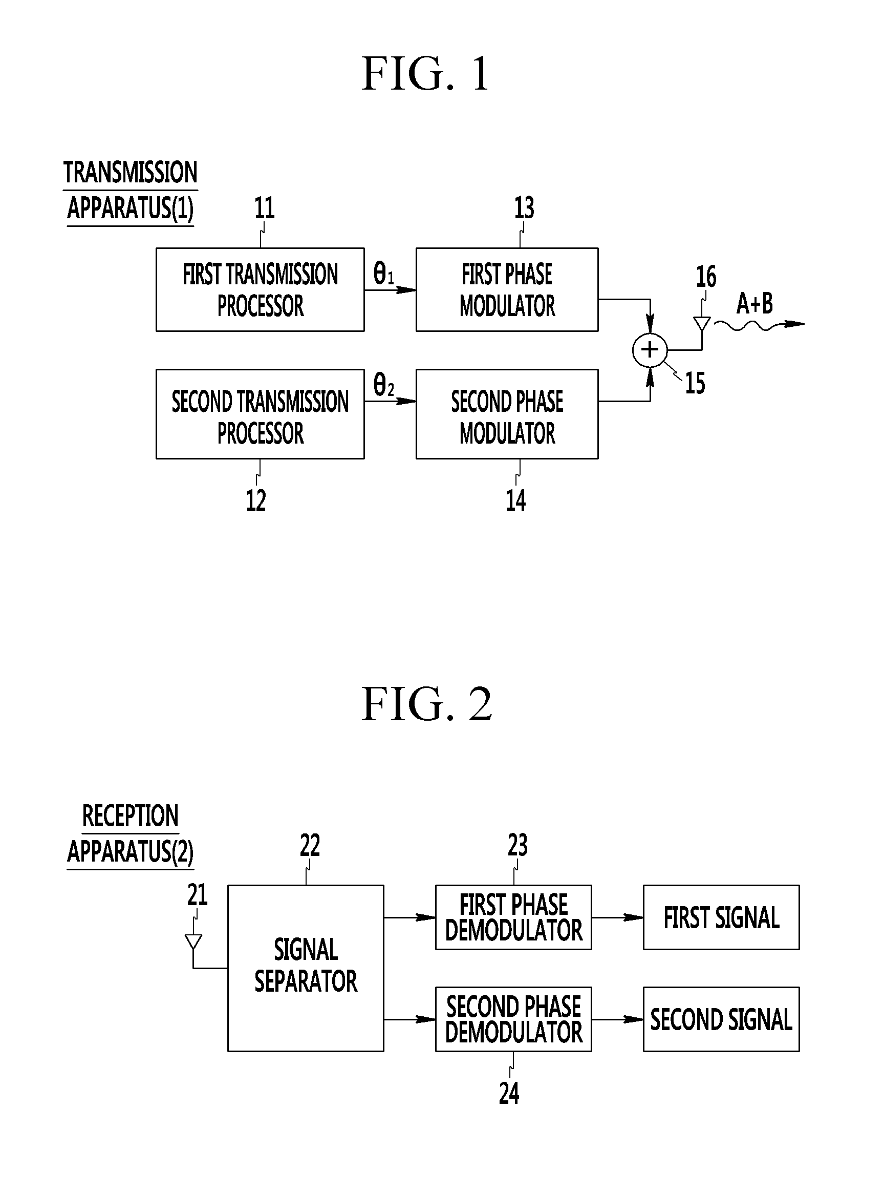
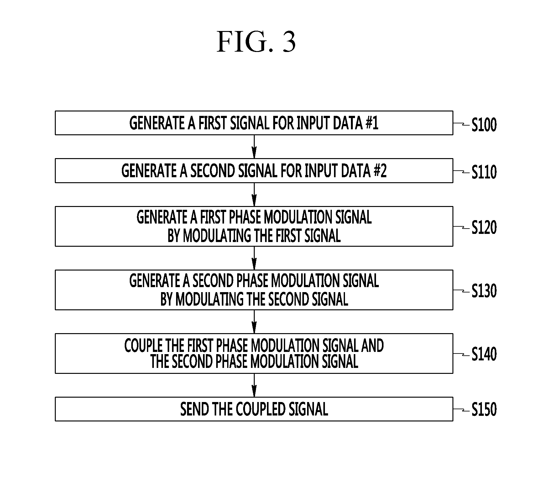
A transmission apparatus couples a first phase modulation signal for first input data and a second phase modulation signal for second input data according to a first coupling method and transmits the coupled signal, and a reception apparatus receives the coupled signal. The reception apparatus derives a signal in which a first phase modulation signal and a second phase modulation signal are coupled according to a second coupling method from a received signal and separates the first phase modulation signal and the second phase modulation signal from the received signal based on the received signal and the derived signal. Furthermore, the reception apparatus obtains the first input data by demodulating the first phase modulation signal and obtains the second input data by demodulating the second phase modulation signal.

Description

CROSS-REFERENCE TO RELATED APPLICATION[0001]This application claims priority to and the benefit of Korean Patent Application Nos. 10-2012-0047094 and 10-2013-0043769 filed in the Korean Intellectual Property Office on May 3, 2012 and Apr. 19, 2013, the entire contents of which are incorporated herein by reference.BACKGROUND OF THE INVENTION[0002](a) Field of the Invention[0003]The present invention relates to a method and apparatus for transmitting and receiving signals.[0004](b) Description of the Related Art[0005]Amplitude modulation is a modulation scheme for changing the amplitude of a carrier depending on the intensity of an information signal and is characterized in that it is vulnerable to fading due to the multipath of radio waves and it has a high Peak-to-Average Power Ratio (PAPR) versus average power.[0006]Meanwhile, phase modulation is characterized in that the amplitude of a carrier is constant because an information signal is carried on the phase of the carrier and the...

Claims


Application Information

Patent Timeline
Patent Type & Authority Applications(United States)
IPC IPC(8): H04L5/12
CPCH04L5/12H04L27/18H04L27/34
Inventor LIM, JONG SOOKWON, SUN HYOUNGKIM, HEUNG MOOKHUR, NAMHO
Owner ELECTRONICS & TELECOMM RES INST
Learn More