Pipe-laying vessel and method of laying a pipeline

a technology of pipe-laying vessels and pipelines, applied in the direction of pipe-laying vessels, pipe laying and repair, mechanical equipment, etc., can solve the problems of reducing the likelihood of structure fatigue, vessel is more likely to be able to pass under bridges or other overhead obstructions,

Active Publication Date: 2013-11-07
SAIPEM SPA
View PDF9 Cites 6 Cited by
  • Summary
  • Abstract
  • Description
  • Claims
  • Application Information

AI Technical Summary

Benefits of technology

[0006]The present invention provides, according to a first aspect, a pipe-laying vessel including a pipe-laying tower extending upwardly from the vessel, the tower comprising a first lower section extending upwardly from a proximal end to a distal end above the main deck of the vessel, and a second upper section movably mounted on the first lower section, and the tower having a first pipe-laying configuration for laying pipeline in which the upper section is positioned above the lower section and pipe is passed from the upper section to the lower section when, in use, it is being laid, and a second stowed configuration in which the second upper section is moved relative to the lower section and the overall height of the tower is reduced.

Problems solved by technology

It also reduces the likelihood of fatigue in the structure.
In addition, by reducing the overall height of the tower, the vessel is more likely to be able to pass under bridges or other overhead obstructions.

Method used


Image

  • Pipe-laying vessel and method of laying a pipeline
  • Pipe-laying vessel and method of laying a pipeline
  • Pipe-laying vessel and method of laying a pipeline

Examples


Embodiment Construction

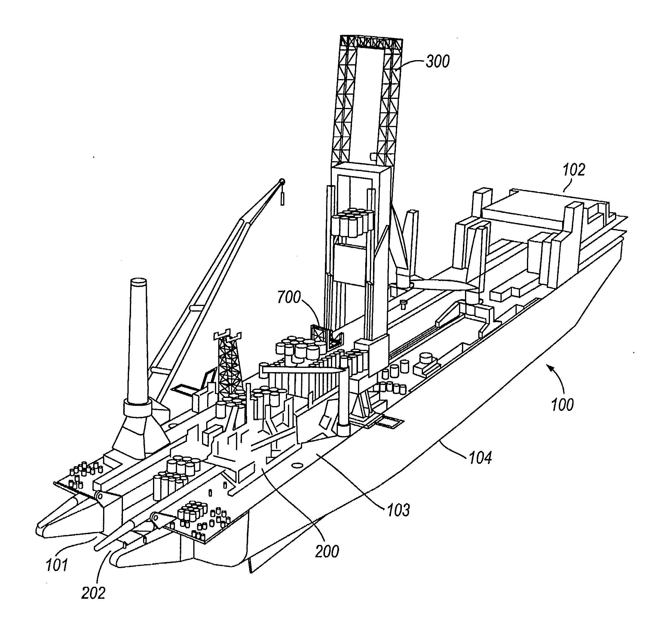
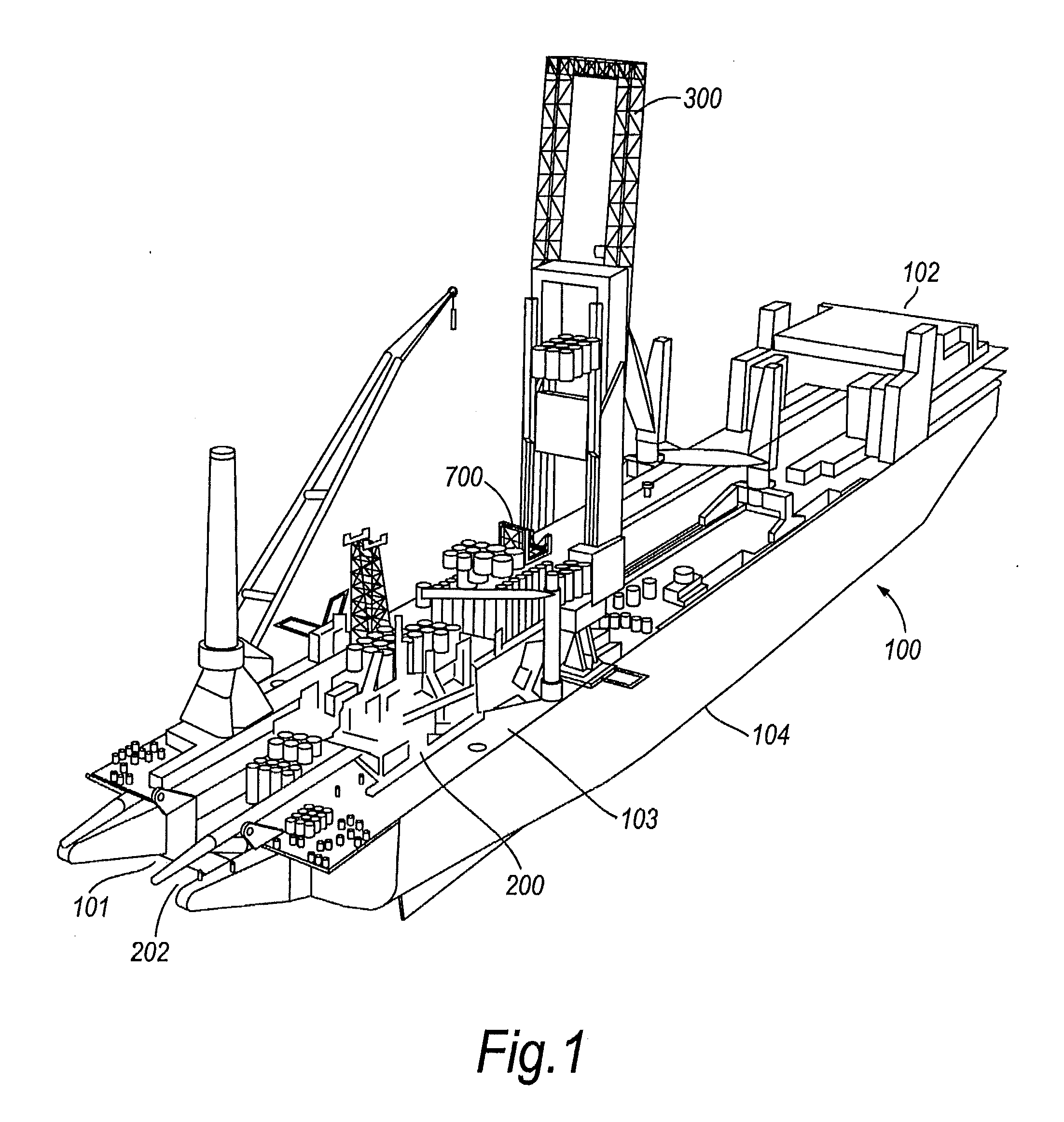
[0099]FIG. 1 shows a pipe-laying vessel 100. The vessel 100 has a bow end 102 and a stern end 101. The bottom of the vessel, known as the keel line, is labelled as 104. On the deck 103 of the vessel, at the stern end 101 are various ramps defining S-laying apparatus 200. Other S laying apparatus is provided towards the bow of the vessel as more fully described in WO2008 / 107186, the contents of which is incorporated herein by reference. At the stern end 101 is an S-lay opening 202 to allow the pipeline to enter the water near the stern of the vessel 100. The vessel 100 also has a J-laying tower 300 in a middle portion of the vessel partway along the firing line for S-laying.

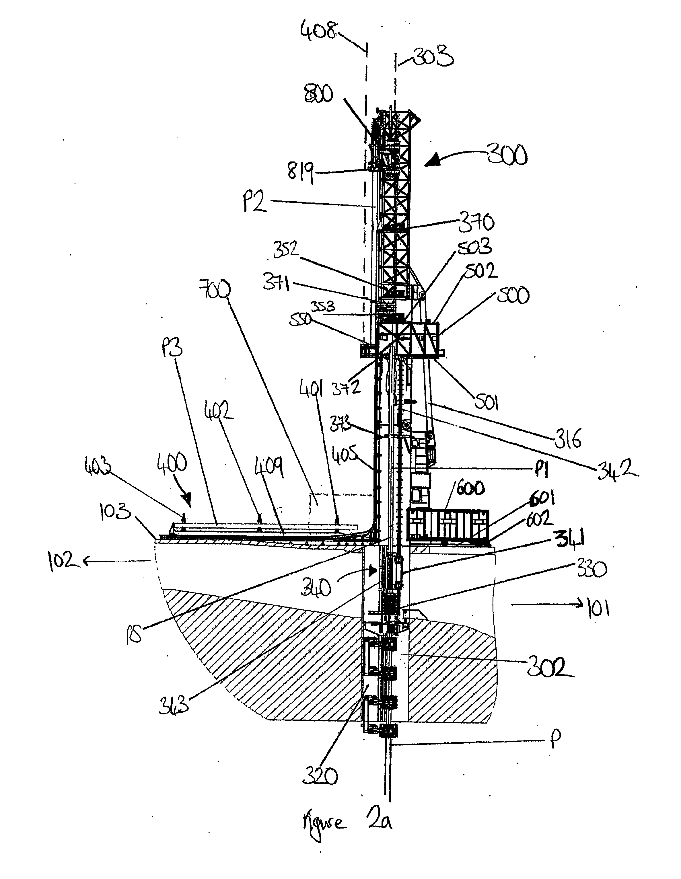
[0100]FIGS. 2a and 2b show more detailed views of the J-lay tower 300 and associated equipment. The tower 300 extends upwards vertically from the deck 103 of the vessel.

[0101]Below the tower is an opening 302 in the hull of the vessel to the water beneath. This opening allows passage of the pipeline P from the tow...


PUM


Abstract

A pipe-laying vessel including a pipe-laying tower extending upwardly from the vessel, the tower including a first lower section extending upwardly from a proximal end to a distal end above the main deck of the vessel, and a second upper section movably mounted on the first lower section, and the tower having a first pipe-laying configuration for laying pipeline P in which the upper section is positioned above the lower section and pipe is passed from the upper section to the lower section when, in use, it is being laid, and a second stowed configuration in which the second upper section is moved relative to the lower section and the overall height of the tower is reduced.

Description

BACKGROUND OF THE INVENTION[0001]This invention relates to pipe-laying vessels and to methods of laying a pipeline. Such vessels and methods are of particular use in the offshore industry relating to oil and gas production.[0002]One of the tasks that is carried out by certain vessels in the offshore industry is that of laying pipelines, either by S-laying or by J-laying.[0003]In “S” laying, the pipeline leaves the vessel at little or no inclination to the horizontal, adopts a steeper inclination in the water and then returns to a generally horizontal disposition on the seabed. The tension in the pipeline is often accommodated by a series of track tensioners mounted along the pipe-laying path, on the vessel. The track tensioners support the weight of the pipeline and control passage of the pipeline. S laying is preferred in shallower water where the natural path of the pipeline is only ever inclined at a shallow angle as it passes to the seabed. Examples of S-laying arrangements are ...

Claims


Application Information

Patent Timeline
Patent Type & Authority Applications(United States)
IPC IPC(8): F16L1/19
CPCF16L1/19B63B35/03F16L1/18F16L1/20F16L1/235
Inventor BIANCHIARDAVANIS, KIMON TULLIOBAYLOT, MICHEL PIERRE ARMANDHAJERI, YANN
Owner SAIPEM SPA
Why Eureka
Try Eureka