Method for enhancing the resolving power of ion mobility separations over a limited mobility range

a technology of mobility separation and ion mobility, applied in the field of analytical separation, can solve the problems of reducing the resolution gain along the path, affecting the resolution, and reducing the resolving power, so as to improve the separation metrics, avoid exceeding the charge capacity of the electrodynamic funnel, and increase the resolving power

Inactive Publication Date: 2013-11-14
BATTELLE MEMORIAL INST
View PDF2 Cites 13 Cited by
  • Summary
  • Abstract
  • Description
  • Claims
  • Application Information

AI Technical Summary

Benefits of technology

[0018]Filtered ions can be transmitted for downstream mass spectrometry (MS), IMS, or IMS / MS analyses. The disclosed methods are capable of rejecting unwanted ions (chemical noise) inevitably produced by known ionization sources. In an application, this helps one to avoid exceeding the charge capacity of electrodynamic funnel or other traps that accumulate ions prior to MS or IMS / MS measurements.

Problems solved by technology

Further resolution gains along this path are impeded by the difficulty and cost of generating, isolating, and safely using voltages much above 10 kV.
While R˜40 attained in that system exceeds the “diffusion limit” defined by drift voltage for a stationary gas by fourfold, it is still much below the best DTIMS benchmarks, and achieving much greater R values is complicated by inevitable flow non-uniformity across the tube.
However, that approach is complex to implement and has poor sensitivity because of large ion losses in successive turns around the loop.
This causes major ion losses and compresses the dynamic range, unless elaborate multiplexing schemes are implemented.
Similarly, the dynamic range of ion trap MS platforms is limited by the ion trap charge capacity.

Method used


Image

  • Method for enhancing the resolving power of ion mobility separations over a limited mobility range
  • Method for enhancing the resolving power of ion mobility separations over a limited mobility range
  • Method for enhancing the resolving power of ion mobility separations over a limited mobility range

Examples


Embodiment Construction

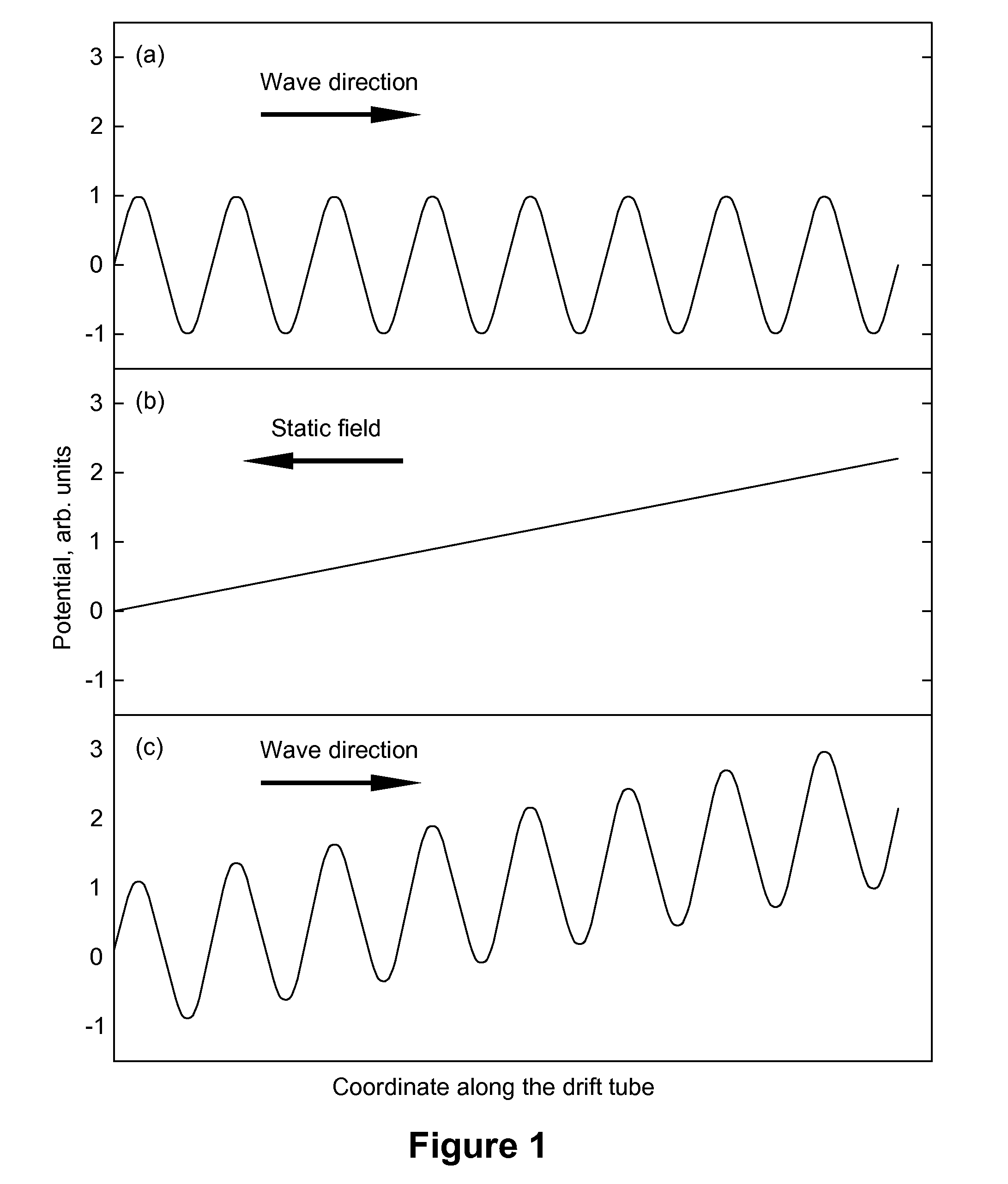
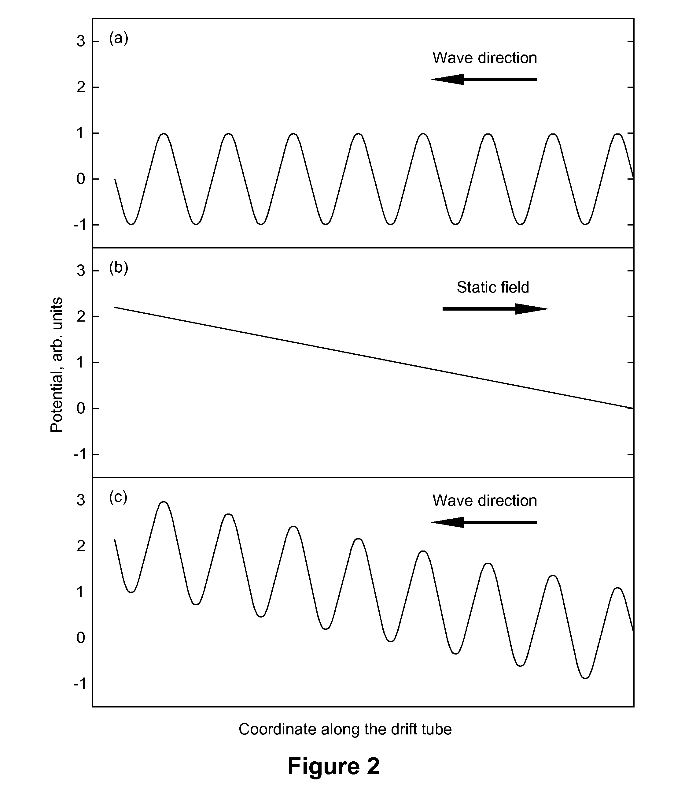
[0022]The resolving power and thus resolution and peak capacity of IMS using the TWIMS paradigm can be significantly raised over a limited mobility range by applying a “retarding” electric field opposite to the direction of oscillatory field wave. This regime enables a “zoom” mode with theoretically unlimited resolving power gain, at the cost of narrower mobility range and extended separation time. The retarding field can be static or an oscillatory wave propagated contrary to the first wave direction with different parameters—the amplitude, waveform profile, frequency, or speed.

[0023]The time-averaged drift velocity of an ion in a field wave depends on its mobility K non-linearly: approximately as K2 over a broad mobility range (Shvartsburg and Smith, Anal. Chem. 2008, 80, 9689). Conversely, the drift velocity in static field is linear with K (rigorously in the low-field limit, but in practice also at moderate fields typical for existing TWIMS implementations). Hence, the combinati...


PUM


Abstract

A method for raising the resolving power, specificity, and peak capacity of conventional ion mobility spectrometry is disclosed. Ions are separated in a dynamic electric field comprising an oscillatory field wave and opposing static field, or at least two counter propagating waves with different parameters (amplitude, profile, frequency, or speed). As the functional dependencies of mean drift velocity on the ion mobility in a wave and static field or in unequal waves differ, only single species is equilibrated while others drift in either direction and are mobility-separated. An ion mobility spectrum over a limited range is then acquired by measuring ion drift times through a fixed distance inside the gas-filled enclosure. The resolving power in the vicinity of equilibrium mobility substantially exceeds that for known traveling-wave or drift-tube IMS separations, with spectra over wider ranges obtainable by stitching multiple segments. The approach also enables low-cutoff, high-cutoff, and bandpass ion mobility filters.

Description

CROSS-REFERENCE TO RELATED APPLICATIONS [0001]This application claims priority to U.S. Provisional Application Ser. No. 61 / 646,748, filed May 14, 2012, titled “METHOD FOR ENHANCING THE RESOLVING POWER OF ION MOBILITY SEPARATIONS OVER A LIMITED MOBILITY RANGE,” hereby incorporated by reference in its entirety for all of its teachings.STATEMENT REGARDING FEDERALLY SPONSORED RESEARCH OR DEVELOPMENT [0002]The invention was made with Government support under Contract DE-AC05-76RLO1830, awarded by the U.S. Department of Energy. The Government has certain rights in the invention.TECHNICAL FIELD [0003]This invention relates to analytical separations and, more specifically, ion mobility spectrometry (IMS).BACKGROUND OF THE INVENTION [0004]IMS involves separation, characterization, or identification of ions based on their transport through gases driven by electric field. In conventional IMS considered here, separation is based on the absolute mobility (K) at moderate field intensity.[0005]As ...

Claims


Application Information

Patent Timeline
Patent Type & Authority Applications(United States)
IPC IPC(8): H01J49/00
CPCH01J49/0031G01N27/622
Inventor SHVARTSBURG, ALEXANDRE A.TANG, KEQISMITH, RICHARD D.
Owner BATTELLE MEMORIAL INST
Why Eureka
Try Eureka