Method and apparatus for transmitting and receiving frame configuration information in TDD wireless communication system

a wireless communication system and frame configuration technology, applied in the direction of multi-channel communication, transmission path division, duplex signal operation, etc., can solve the problems of lte system, to which tdd is applied, and may not cope with the dynamically changing amount of ul/dl data, request for data traffic may significantly and dynamically change, etc., to achieve efficient transmission and receiving configuration information, efficient transmission and receiving changed configuration information

Active Publication Date: 2013-11-14
SAMSUNG ELECTRONICS CO LTD
View PDF14 Cites 56 Cited by
  • Summary
  • Abstract
  • Description
  • Claims
  • Application Information

AI Technical Summary

Benefits of technology

[0032]Accordingly, an aspect of the present invention is to provide a method and apparatus for efficiently transmitting and receiving configuration information of a TDD frame in a wireless communication system.
[0033]Another aspect of the present invention is to provide a method and apparatus for efficiently transmitting and receiving changed configuration information if there is a change in configuration information of a TDD frame in a wireless communication system.

Problems solved by technology

In the case of TDD, if cells have different frame configurations, their transmission / reception may fail due to interference.
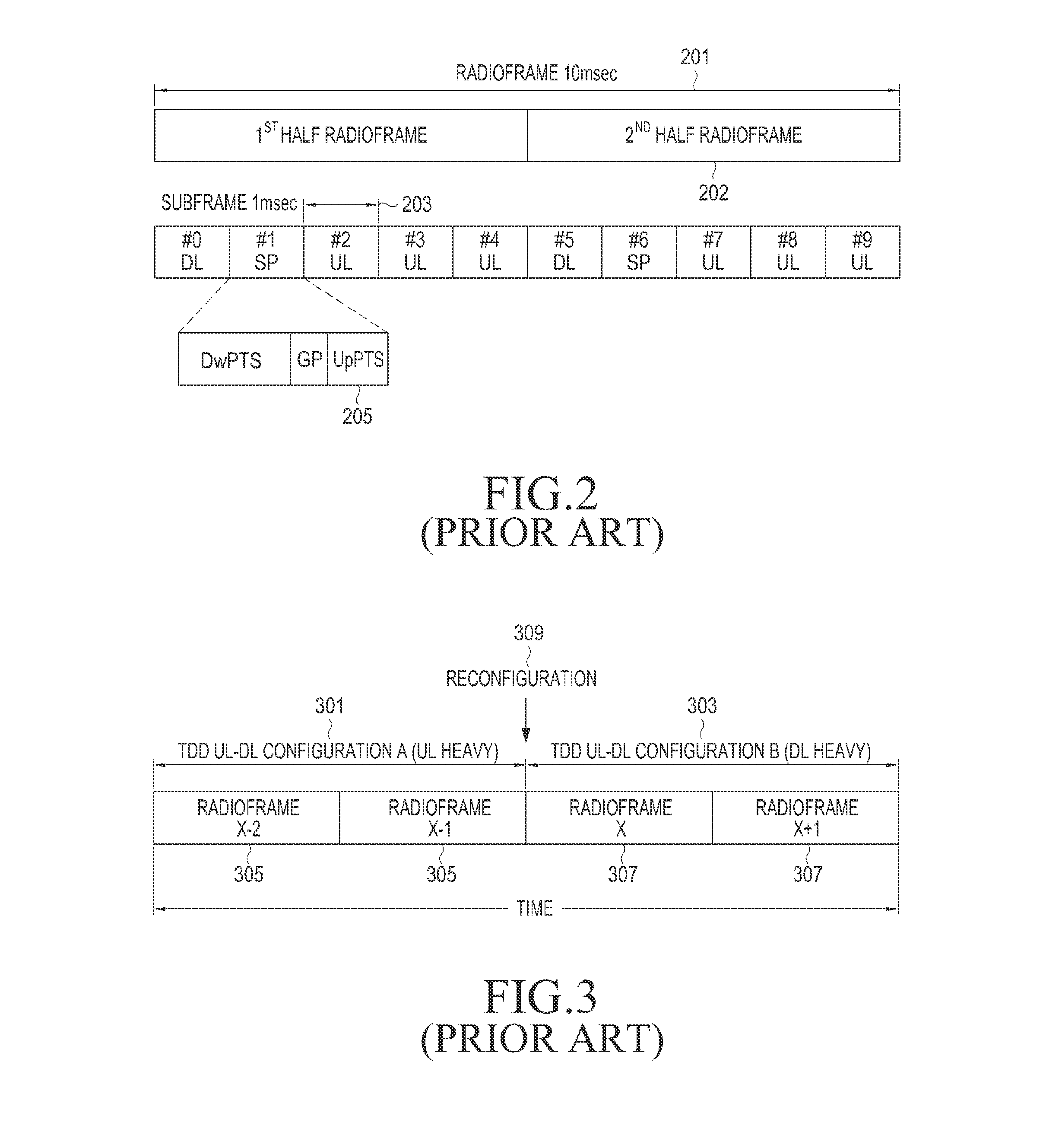
The LTE system, to which TDD is applied, may not cope with the dynamically changing amount of UL / DL data, because once determined, the TDD configuration may not be changed in a short period of time.
In other words, even though a large amount of UL data is generated for a certain period of time, the system may not use a DL sub-frame in a UL interval, for UL transmission.
The area where there is a request for a large amount of data traffic may mean that the request for data traffic may significantly and dynamically change with the passage of time.
However, if a UE needs to transmit a large amount of data to an eNB at a specific time or if there is a large amount of UL VoIP data to transmit, the UE may instantly request a large amount of UL resources from the eNB.
The common TDD system, however, may not appropriately accept this UE's request for UL resources, because the common TDD system is designed such that eNBs connected to the same network may have the same TDD configuration, in order to prevent interference caused by collision of UL transmission and DL transmission between an eNB and a UE, or between neighbor eNBs.
Furthermore, in the TDD system, each eNB needs to independently change its TDD configuration in order to adaptively cope with the variable amount of data traffic, which causes interference, making it impossible to actually transmit data.
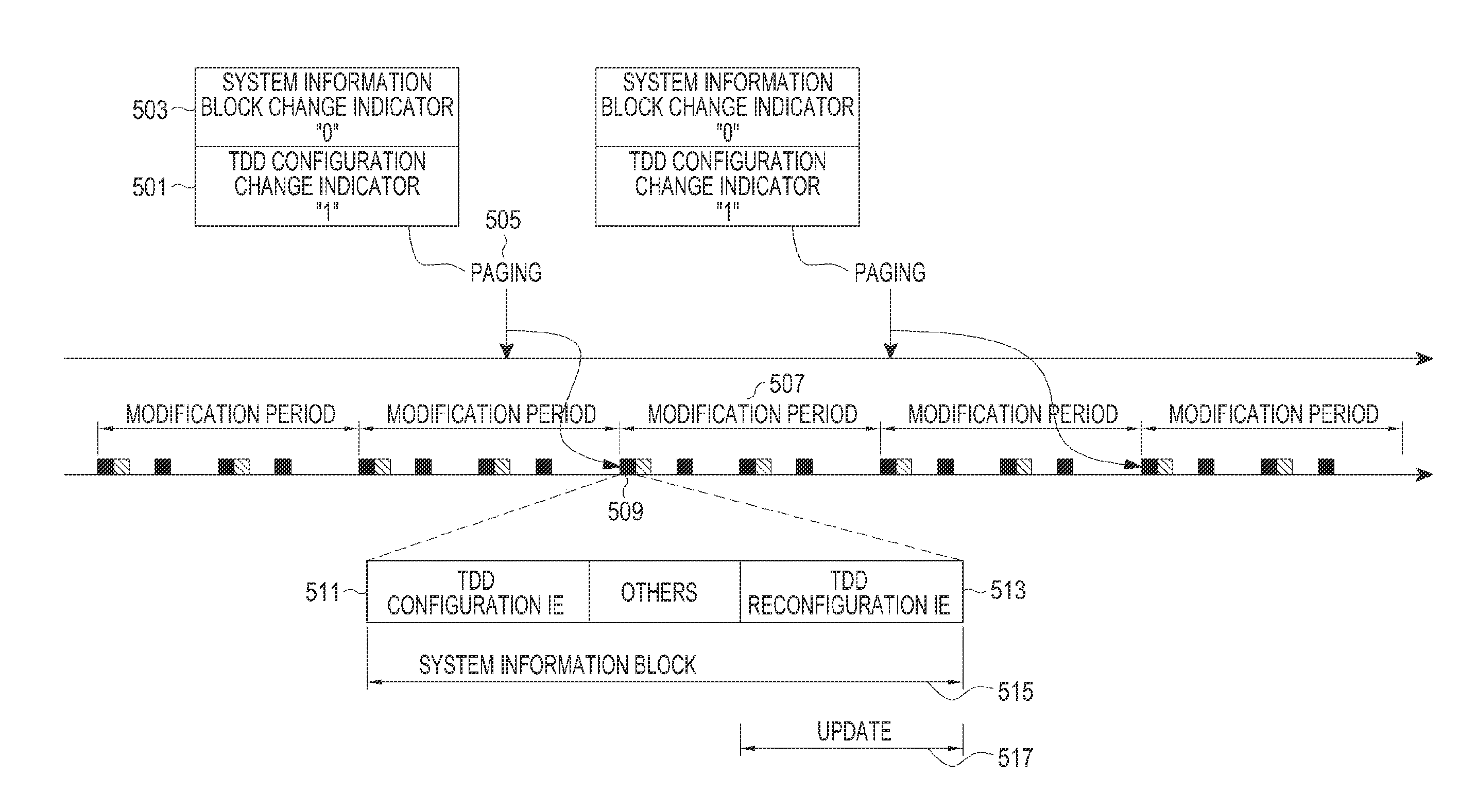
The UE that does not support the dynamic TDD system may not recognize or detect a change in TDD configuration, which is caused by a change in system information.
Therefore, the UE that does not support the dynamic TDD system may not achieve UL data transmission and DL data reception due to the changed TDD configuration, and also may not determine whether the eNB operates the TDD configuration for a DL or for a UL, at the time that the UE performs channel measurement in a DL sub-frame.
As a result, in the dynamic TDD system, the eNB may not manage the UE that does not support the dynamic TDD system.
However, in the LTE system, the above-described existing system information changing method is limited to be applied to the dynamic TDD system, and all UEs need to change the system information.
However, since the existing UE that does not support the dynamic TDD system cannot detect the change in system information, an error may occur between the TDD configuration changed by the eNB and the TDD configuration used by the UE, making the data transmission difficult.
In addition, if an error occurs during reception of system information, this problem becomes more serious.

Method used


Image

  • Method and apparatus for transmitting and receiving frame configuration information in TDD wireless communication system
  • Method and apparatus for transmitting and receiving frame configuration information in TDD wireless communication system
  • Method and apparatus for transmitting and receiving frame configuration information in TDD wireless communication system

Examples


Embodiment Construction

[0052]The following description with reference to the accompanying drawings is provided to assist in a comprehensive understanding of various embodiments of the present invention as defined by the claims and their equivalents. It includes various specific details to assist in that understanding but these are to be regarded as merely exemplary. Accordingly, those of ordinary skilled in the art will recognize that various changes and modifications of the embodiments described herein can be made without departing from the scope and spirit of the invention. In addition, descriptions of well-known functions and constructions may be omitted for clarity and conciseness. Throughout the drawings, like reference numerals will be understood to refer to like parts, components, and structures.

[0053]The terms and words used in the following description and claims are not limited to the bibliographical meanings, but, are merely used to enable a clear and consistent understanding of the invention. ...


PUM


Abstract

A method and apparatus for transmitting Time Division Duplexing (TDD) configuration information by an evolved Node B (eNB) in a TDD wireless communication system are provided. The method includes determining a changed TDD configuration indicating a transmission direction of a plurality of sub-frames constituting a frame; generating a system information element including dynamic TDD configuration information indicating the changed TDD configuration; transmitting a system information block including the dynamic TDD configuration information; and sending a Media Access Control (MAC) message including information indicating whether a change in TDD configuration is activated.

Description

PRIORITY[0001]This application claims the benefit under 35 U.S.C. §119(a) of a United States (U.S.) provisional patent application filed in the U.S. Patent and Trademark Office on May 10, 2012 and assigned Ser. No. 61 / 645,221, the entire disclosure of which is incorporated herein by reference.BACKGROUND OF THE INVENTION[0002]1. Field of the Invention[0003]The present invention relates generally to a method and apparatus for transmitting and receiving system information related to the configuration of a frame in a Time Division Duplexing (TDD) wireless communication system.[0004]2. Description of the Related Art[0005]Wireless communication systems, which provided voice-driven services in their early stages, have developed into high-speed, high-quality wireless packet data communication systems to provide data services and multimedia services. As these wireless communication systems, a variety of wireless communication systems, such as High Speed Downlink Packet Access (HSDPA), High S...

Claims


Application Information

Patent Timeline
Patent Type & Authority Applications(United States)
IPC IPC(8): H04L5/14
CPCH04L5/14H04L5/0007H04L5/0044H04L5/0096H04L5/1469H04W72/23
Inventor JI, HYOUNG-JUCHO, JOON-YOUNGCHOI, SEUNG-HOONKIM, YOUNG-BUMRO, SANG-MIN
Owner SAMSUNG ELECTRONICS CO LTD
Why Eureka
Try Eureka