Vehicle Seat Scissors Suspension With Integrated Stabilized Isolator

a technology of isolator and scissors, which is applied in the direction of machine supports, movable seats, rod connections, etc., can solve the problems of increasing interference and friction between tracks and rollers, undesirable interference and friction, and disadvantages of conventional isolators, so as to improve isolator performance and reduce the operational envelope

Active Publication Date: 2013-11-21
SEARS MFG
View PDF1 Cites 21 Cited by
  • Summary
  • Abstract
  • Description
  • Claims
  • Application Information

AI Technical Summary

Benefits of technology

[0005]The present invention is directed to a vehicle seat suspension having a stabilized or guided isolator system that overcomes the disadvantages of the prior art. Moreover, the present invention provides enhanced isolator performance in a mechanically simple, reliable and inexpensive design. Importantly, the present invention integrates the isolator function in a scissors suspension assembly so that the overall apparatus is more compact and requires a smaller operational envelope.

Problems solved by technology

These conventional isolators, however, suffer from certain disadvantages.
Because of dimensional and tolerance constraints, these prior art isolator systems have a tendency to cant or “rack,” increasing the interference and friction between the tracks and rollers.
In addition, when the vehicle is on uneven terrain, which is often the case with off-the-road vehicles, the isolator tracks may bear against the sides of rollers, again generating undesirable interference and friction.
Either or both of these problems can reduce the useful life of the suspension or require repair.
Finally, the prior art isolators may cause a perceived “looseness” in the seat ride which is undesirable to the occupant.
While the disclosed apparatus is functionally satisfactory, the disclosed scissors suspension assembly and isolator are separate components thereby adding to its cost and space requirements.

Method used


Image

  • Vehicle Seat Scissors Suspension With Integrated Stabilized Isolator
  • Vehicle Seat Scissors Suspension With Integrated Stabilized Isolator
  • Vehicle Seat Scissors Suspension With Integrated Stabilized Isolator

Examples


Embodiment Construction

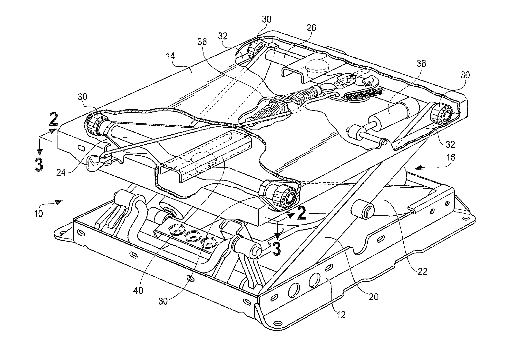
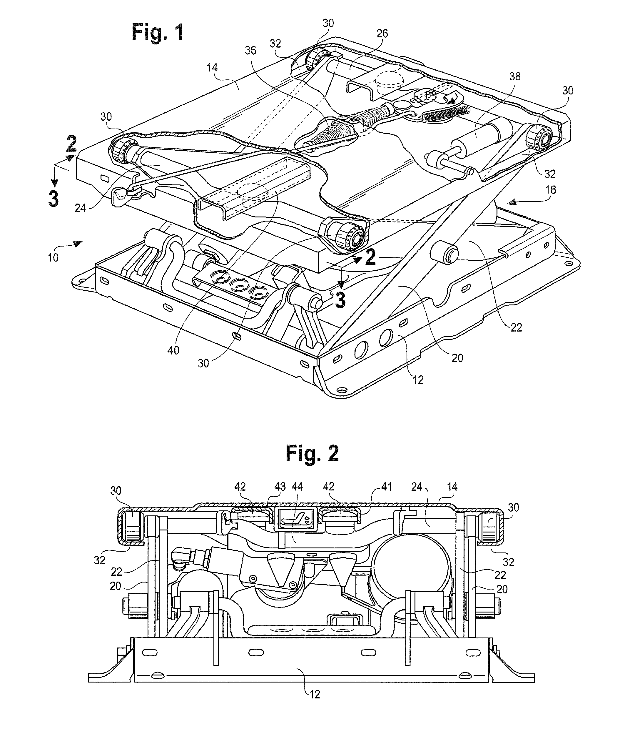
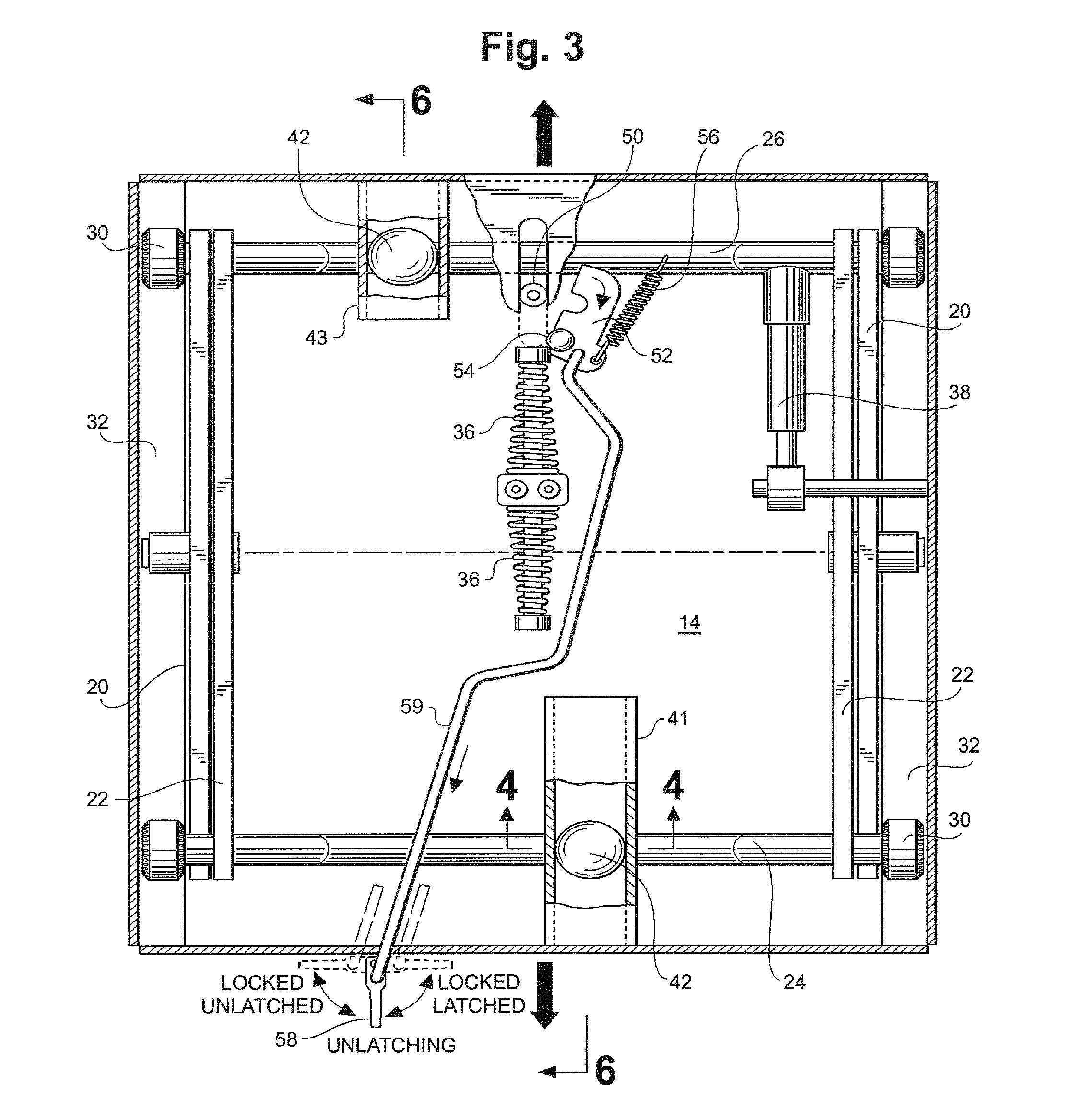
[0014]With reference to FIGS. 1 and 2, the improved seat suspension of the present invention is designated generally as 10, and includes a lower housing or base 12, an upper housing or platform 14 and a scissors linkage assembly 16. The scissors linkage assembly is well known to those of skill in the art and will not be disclosed here in any detail. However, it is generally comprised of two pair of scissors links, each link of the outer pair designated as 20 and each link of the inside pair being designated as 22. In addition, a front cross member or shaft 24 connects the upper ends of the inside links 22, while a rear cross member or shaft 26 connects the upper ends of the outside links 20. Side rollers 30 are positioned adjacent to the upper ends of links 20 and 22 and extend laterally outward from those links along generally horizontal axes of rotation. The upper housing 14 includes longitudinally extending side tracks 32 which house side rollers 30, thereby permitting the upper ...


PUM


Abstract

A vehicle seat suspension comprises a scissors assembly connecting lower and upper housings and permitting vertical movement of the upper housing; reciprocating means; an elongated guide member; and guide engaging rollers. Laterally extending front and rear cross members engage upper ends of the scissor links. The reciprocating means allows the upper housing to move fore and aft, and includes horizontally disposed rollers supported by the scissors assembly and received within side tracks forming part of the upper housing. The guide member is mounted to the upper housing and oriented parallel to the fore and aft travel path. Two vertically disposed guide engaging rollers are mounted to the scissors assembly cross members. The guide engaging rollers cooperate with the guide member at spaced locations to stabilize the upper housing in a direction generally perpendicular to its fore and aft travel path.

Description

BACKGROUND[0001]The present invention is directed generally to vehicle seating. More particularly, the invention is directed to a vehicle seat suspension employing a scissors suspension assembly and having an integrated isolator system that is stabilized to enhance seat suspension performance.[0002]It is now common in vehicle seat technology to provide mechanisms or systems that reduce the undesirable effects of forces inputted to the seat from the front, back or sides. These so called “isolators,” both “fore and aft” and “lateral” varieties, commonly have an isolator plate with side tracks that travels in a reciprocal manner on a set of rollers. These conventional isolators, however, suffer from certain disadvantages. Because of dimensional and tolerance constraints, these prior art isolator systems have a tendency to cant or “rack,” increasing the interference and friction between the tracks and rollers. In addition, when the vehicle is on uneven terrain, which is often the case w...

Claims


Application Information

Patent Timeline
Patent Type & Authority Applications(United States)
IPC IPC(8): B60N2/04B60N2/06B60N2/16
CPCB60N2/507B60N2/50B60N2/501B60N2/502B60N2/503B60N2/504B60N2/505B60N2/508B60N2/509B60N2002/0212F16B7/10
Inventor BRODERSEN, COLE T.
Owner SEARS MFG
Why Eureka
Try Eureka