T beam sling and hoisting method thereof

A hoisting method and technology of a hoisting tool are applied in the field of bridge construction auxiliary equipment, which can solve problems such as difficulty in penetrating the hoisting ring, overturning of the beam body, increase in working time and labor intensity, etc. The effect of reducing the risk of shedding

Pending Publication Date: 2018-05-08
湖南省交通水利建设集团有限公司 +1
View PDF0 Cites 0 Cited by
  • Summary
  • Abstract
  • Description
  • Claims
  • Application Information

AI Technical Summary

Problems solved by technology

Adopt above-mentioned steel wire rope to carry out hoisting prefabricated T-beam and mainly have the following deficiencies: the one, when the suspension ring that steel wire rope is braided passes through the reserved hole, because the diameter of steel wire rope is big, the suspension ring penetrates more difficult, has increased working time and labor intensity; The first is to use large-diameter wire ropes for hoisting, which is not only costly but also has a short service life; third, after the T-beam is hoisted in place, it is easy to disturb the beam body when the wire rope is taken out, resulting in the overturning accident of the beam body
Although the steel sling has a long service life, low cost and relatively easy installation, it still has the following defects:
[0004] 1. The maximum bearing point of lifting is on the steel pin, and the steel pin is divided into left steel pin and right steel pin. After repeated use, the steel pin will come out of the strip hole, which will lead to Hoisting safety accidents, there is a risk of smashing and bruising;
[0005] 2. When lifting, rely on four hooks to hook the hoisting holes at both ends of the steel sling, the operating range spans a large span, and there is a safety risk;
[0006] 3. The steel sling passes through the top of the T-beam and reaches the bottom of the T-beam. The hoisting center is low, which makes hoisting more laborious and unstable, and the risk of hoisting is greater

Method used


Image

  • T beam sling and hoisting method thereof
  • T beam sling and hoisting method thereof
  • T beam sling and hoisting method thereof

Examples


Embodiment

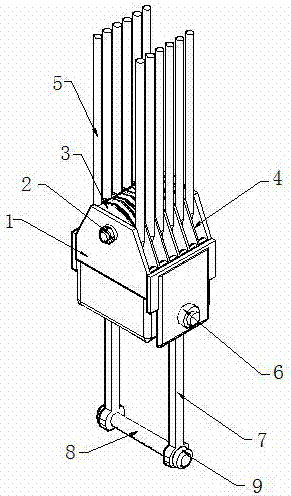
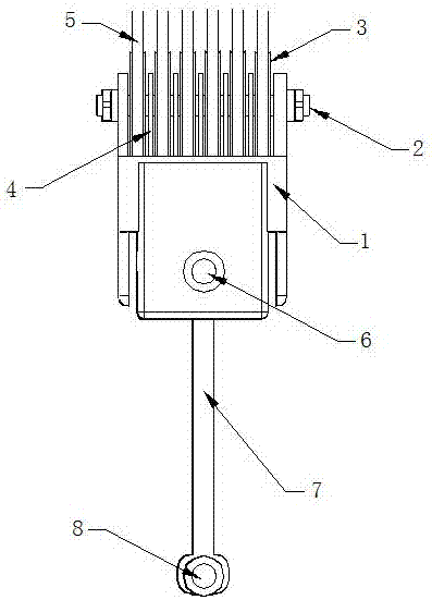
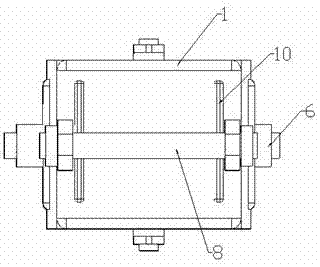
[0037] Such as Figure 1-3 As shown, the T-beam spreader of the present invention includes a body 1, the top and bottom of which are open, and the upper part of the body 1 is equipped with a sheave set composed of a plurality of winding sheaves 3 through a fixed shaft 2, each winding A steel wire rope 5 is wound on the sheave 3, and a plurality of baffles 4 are welded and fixed at equal distances on the body 1 to separate each winding sheave 3; the left and right ends of the lower part of the body 1 are fixed with two Each steel boom 7, the installation shaft 6 is positioned at the inner side of two steel booms 7, each is fixed with the spacer 10 that is used to limit the lateral movement of the steel boom 7, and the bottom of each steel boom 7 has a bolt hole 701 A bearing pin 8 passes through the bolt holes 701 on the two steel suspension arms 7 and is threaded with a safety nut 9 at both ends of the bearing pin 8 and on the outside of the steel suspension arms 7 .

[0038]...


PUM


Abstract

The invention discloses a T beam sling and a hoisting method thereof. The T beam sling comprises a body. The upper portion of the body is provided with a winding sheave matched with a steel wire rope.The lower portion of the body is provided with two vertical parallel steel lazy arms. A bearing pin capable of being detached is arranged between the bottoms of the two steel lazy arms. The T beam sling can hoist a T beam with the span being 50 m and the weight being about 180 tons. The T beam sling and the hoisting method thereof have the beneficial effects that cost is low, the using period islong, hoisting is more stable, and safety and convenience are achieved.

Description

technical field [0001] The invention relates to a T-beam hanger and a hoisting method thereof, belonging to the field of bridge construction auxiliary equipment. Background technique [0002] In the construction of roads and bridges, prefabricated T-beams need to be hoisted, and the conventional method of hoisting is to first pass the rings braided by steel wire ropes through the reserved holes on the upper wing of the T-beams, then bypass the bottom of the prefabricated T-beams, and then pass them through the prefabricated T-beams Go through the reserved hole on the other side of the upper wing of the T-shaped beam, and finally hang the rings at both ends of the wire rope on the hook of the crane in a pocket-like manner, and then start lifting. Adopt above-mentioned steel wire rope to carry out hoisting prefabricated T-beam and mainly have the following deficiencies: the one, when the suspension ring that steel wire rope is braided passes through the reserved hole, because ...

Claims


Application Information

Patent Timeline
Patent Type & Authority Applications(China)
IPC IPC(8): B66C1/12B66C1/64
CPCB66C1/122B66C1/64
Inventor 卢治国朱忠民黄智斌钟阳梁社德
Owner 湖南省交通水利建设集团有限公司
Why Eureka
Try Eureka