Lens hood device, and image pickup device using the same

A hood and lens technology, which is applied to optics, camera bodies, filters for photography, etc., can solve the problem that the lens cover 105 that may be shaken by the lens cover rope 106 that interferes with photography hits the video recorder body 101, the lens, etc. The cover 105 is detached, etc., to protect the lens and improve the operability.

Inactive Publication Date: 2007-11-28
PANASONIC CORP
View PDF2 Cites 13 Cited by
  • Summary
  • Abstract
  • Description
  • Claims
  • Application Information

AI Technical Summary

Problems solved by technology

[0017] (2) As shown in FIG. 34, when the lens cap 105 is attached to the video recorder main body 101, only the pair of engagement claws 105b provided on the rear side of the lens cap 105 are engaged with the inner peripheral groove 104a of the lens hood 104. Therefore, there is a possibility that the lens cover 105 may be easily detached from the video recorder main body 101 due to the shock generated when the video recorder main body 101 is dropped.
[0018] (3) When shooting, as shown in FIG. 34, when the lens cap 105 is hung down from the video recorder main body 101 with the lens cap cord 106, since the lens cap 105 can move freely, it may hinder the shooting.
[0020] (5) As shown in FIG. 35 , when the lens cover 105 is mounted on the holding protrusion 107 and fixed to the handle of the main body and then photographed, due to weak fitting between the hole 105 a and the protrusion 107 a or an impact applied from the outside, etc., the lens cover 105 may be detached from the holding protrusion 107 and become the state shown in FIG. 34
If it becomes the state shown in FIG. 34 during shooting, the lens cap 105 shaken by the lens cap rope 106 may hit the video recorder main body 101, and the impact sound at the time of collision may be recorded.
[0021] (6) In the state where the main body 101 of the video recorder is directed toward the photographing object (subject), the position of the holding protrusion 107 is located in a blind spot, and it is difficult to attach the lens cap 105 to the handle of the main body.
Even if the lens cover 105 is to be attached to the holding protrusion 107 in this state, the protrusion 107a cannot be easily inserted into the hole 105a.

Method used


Image

  • Lens hood device, and image pickup device using the same
  • Lens hood device, and image pickup device using the same
  • Lens hood device, and image pickup device using the same

Examples


Embodiment approach 1

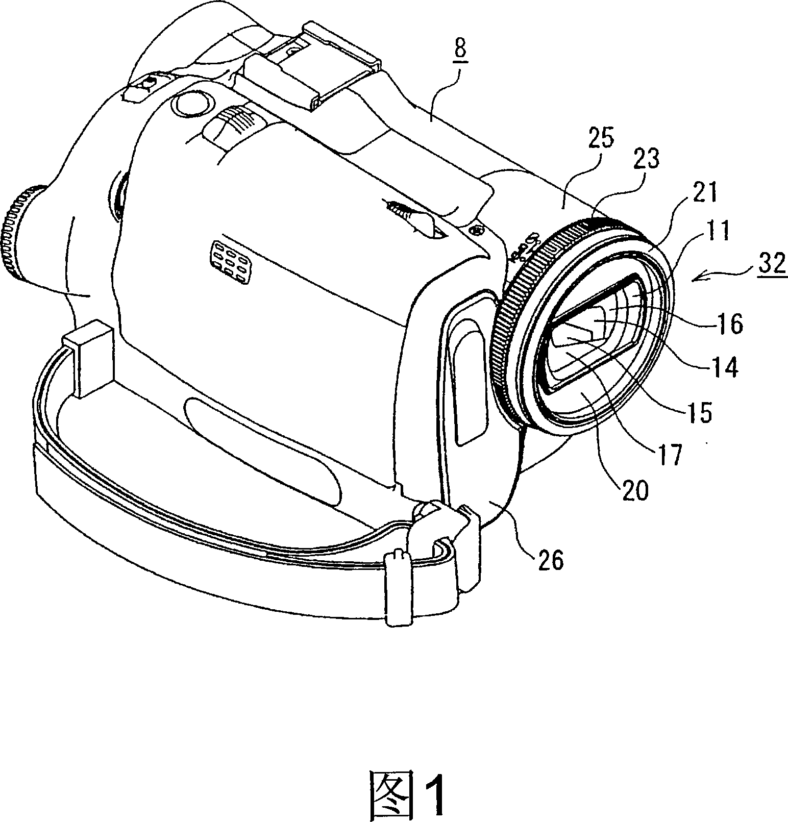
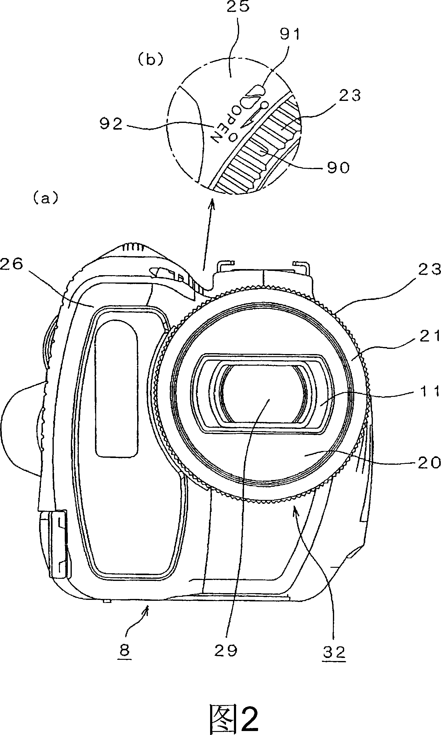
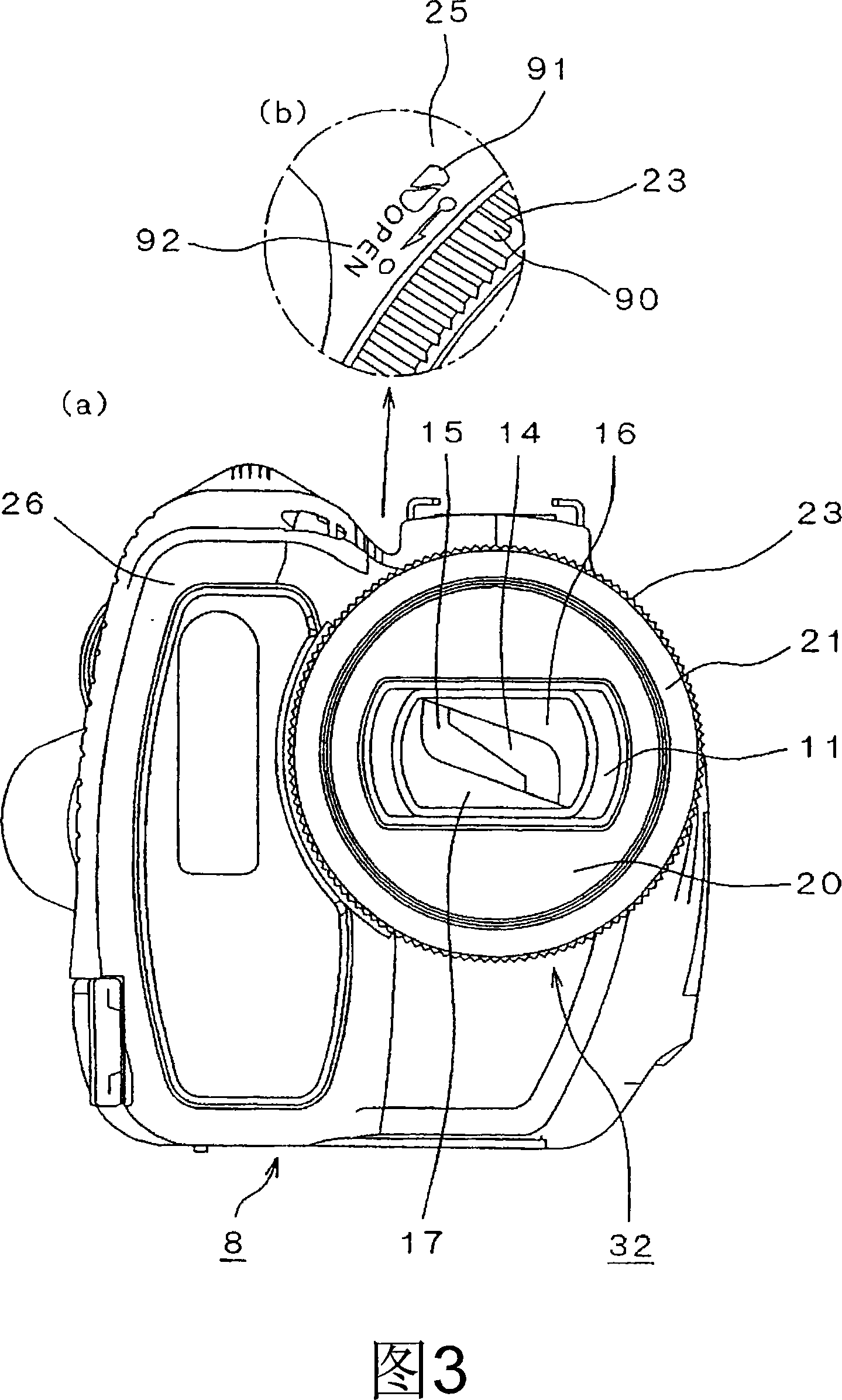
[0076] FIG. 1 is a perspective view showing the configuration of an imaging device housing a lens barrier unit according to Embodiment 1 of the present invention. 2( a ) and FIG. 2( b ) are a front view and a main part perspective view showing a state in which the lens barrier of the imaging device is opened. 3( a ) and FIG. 3( b ) are a front view and a main part perspective view showing a state where the lens barrier is closed. 4(a) and 4(b) are perspective views of the lens barrier unit. 5 to 10 are exploded perspective views and front views showing the structure of the lens barrier unit. 11 to 14 are exploded perspective views showing the structure of the front unit having a shutter opening and closing mechanism.

[0077] As shown in FIG. 1 , the camera body 8 incorporates an imaging element (CCD image sensor, etc.) that converts incident light signals into electrical signals, that is, video signals, and an information storage medium that records the video signals genera...

Embodiment approach 2

[0199] FIG. 28 is a perspective view showing the configuration of the imaging device in Embodiment 1. FIG. FIG. 29 is an exploded perspective view showing the component configuration of the front portion of the imaging device in Embodiment 2. FIG. In addition, in the configuration of Embodiment 2 shown in FIG. 28 , constituent elements having the same numbers as those in Embodiment 1 are assigned the same functions and operations, and detailed description thereof will be omitted.

[0200] In FIG. 28 , the difference from the structure of Embodiment 2 is that there are no closing marks 91 and opening marks 92 shown in FIG. 1 and FIG. 2( b ).

[0201] In addition, in FIG. 29 , a notch portion 26 b for arranging a motor 41 and a two-stage gear 43 (described later) is formed in the front case 26 .

[0202] The ring 40 is rotatably arranged between the lens cover 25 and the front frame 28 . In addition, a coupling portion 40a is formed on the ring 40, and is coupled to the projec...


PUM


Abstract

The peresent invention provides a lens hood device comprises a barrier case (11) covering the front and back of a lens barrier unit (32) in an optical axis direction and having a non-circular opening at a position passed by the optical axis, and a plurality of lens barriers (14 to 17) arranged turnably in parallel with a main flat face of the barrier case (11) and made turnable between a position to cover the whole face of the opening and a position to open the opening. The lens barriers (14 to 17) are so housed in the barrier case (11), when they are positioned to open the opening, as not to be exposed to the opening. The lens hood device provided can improve the operability without enlarging the size of an image pickup device.

Description

technical field [0001] The present invention relates to a lens hood device effectively used in imaging devices such as video recorders and digital cameras. Background technique [0002] Generally, in video recording, a lens hood device is attached to the front end of the lens of the main body to prevent stray light from entering the lens. In addition, when the video recorder is not in use, a lens cap is attached to the subject-side front end of the lens barrel of the main body to protect the lens (for example, refer to Patent Documents 1 to 3). [0003] Hereinafter, conventional lens hoods and lens caps will be described. [0004] 32 to 35 show a state where a conventional lens hood and lens cap are attached to the main body of the video recorder. Fig. 32 is a perspective view showing a state where the lens cap and the lens hood are detached. 33 is a perspective view showing a state where a lens hood and a lens cap are attached to the video recorder main body. Fig. 34 is...

Claims


Application Information

Patent Timeline
Patent Type & Authority Applications(China)
IPC IPC(8): G03B11/04G03B17/02
Inventor 尾川智彦天野浩己森安义忠
Owner PANASONIC CORP
Why Eureka
Try Eureka