Sawtooth wave generation circuit

Inactive Publication Date: 2013-11-21
PANASONIC SEMICON SOLUTIONS CO LTD
View PDF0 Cites 4 Cited by
  • Summary
  • Abstract
  • Description
  • Claims
  • Application Information

AI Technical Summary

Benefits of technology

[0021]The present invention is configured as described above, and provides an advantage of being able to readily generate, using one ou

Problems solved by technology

In particular, it is difficult to form the sawtooth wave generation circuit in an integrated circuit.
Moreover, there is a problem in t

Method used


Image

  • Sawtooth wave generation circuit
  • Sawtooth wave generation circuit
  • Sawtooth wave generation circuit

Examples


Example

Embodiment 1

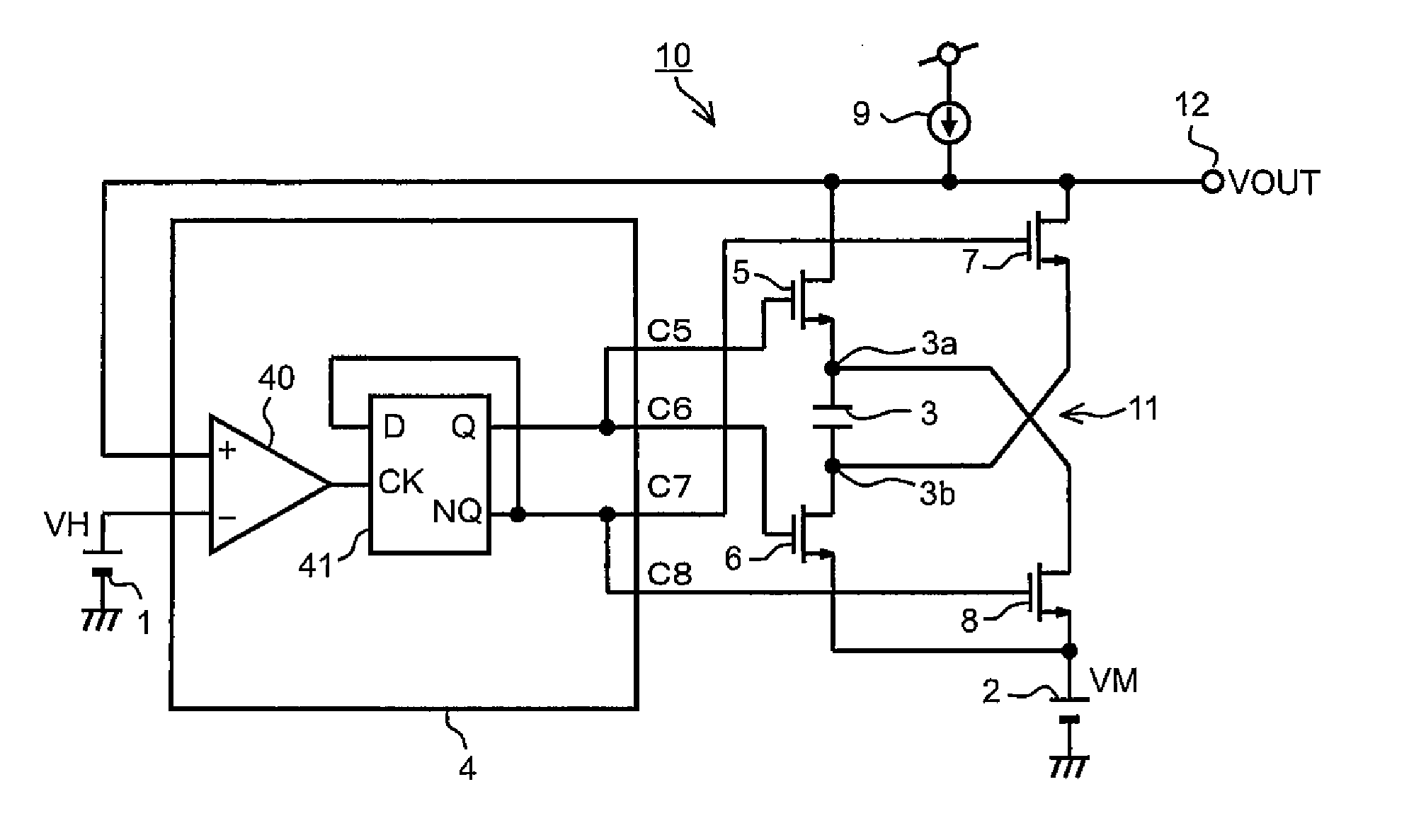
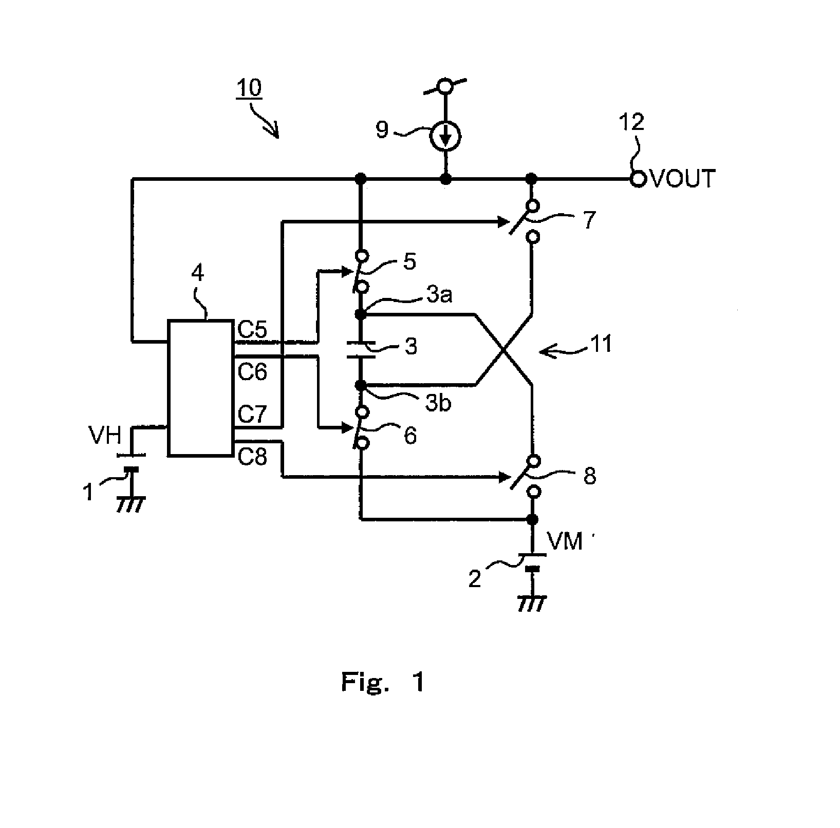
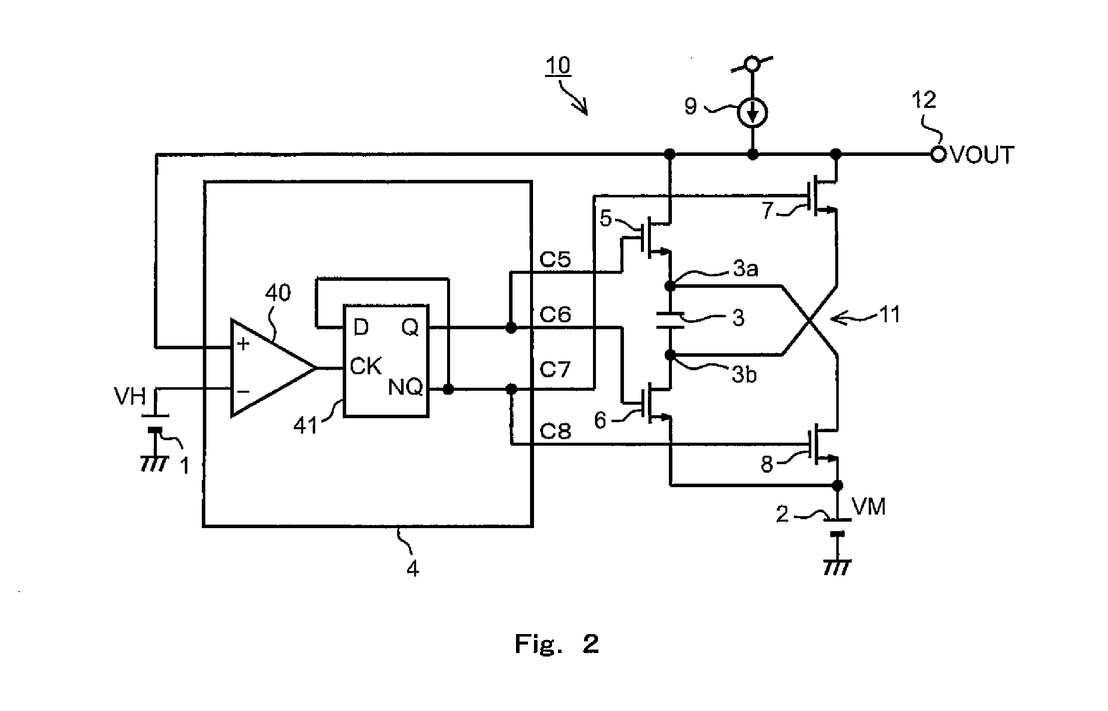
[0031]First, a sawtooth wave generation circuit according to Embodiment 1 of the present invention is described. FIG. 1 is a circuit diagram showing a schematic configuration of the sawtooth wave generation circuit according to Embodiment 1 of the present invention.

[0032]As shown in FIG. 1, a sawtooth wave generation circuit 10 according to the present embodiment includes: an output capacitor 3 including a first terminal 3a and a second terminal 3b; a current source 9 configured to supply a current to the output capacitor 3; a switch circuit 11 configured to switch the flow direction of the current to the output capacitor 3; and an output terminal 12. The switch circuit 11 switches a connection state thereof between a first connection state and a second connection state. In the first connection state, the current from the current source 9 flows from the first terminal 3a to the second terminal 3b of the output capacitor 3. In the second connection state, the current from...

Example

Embodiment 2

[0052]Next, a sawtooth wave generation circuit according to Embodiment 2 of the present invention is described. FIG. 4 is a circuit diagram showing a schematic configuration of the sawtooth wave generation circuit according to Embodiment 2 of the present invention. In the present embodiment, the same components as those described in Embodiment 1 are denoted by the same reference signs as those used in Embodiment 1, and a description of such components is omitted. A sawtooth wave generation circuit 10B according to the present embodiment is different from the sawtooth wave generation circuit 10 according to Embodiment 1 in that, in the sawtooth wave generation circuit 10B, a switch control circuit 4B performs control such that a dead time is provided between the first connection state and the second connection state. In the dead time, a switch circuit 11B prevents a current in any direction from flowing to the output capacitor 3. Specifically, in the present embodiment, i...

Example

Embodiment 3

[0062]Next, a sawtooth wave generation circuit according to Embodiment 3 of the present invention is described. FIG. 5 is a circuit diagram showing a schematic configuration of the sawtooth wave generation circuit according to Embodiment 3 of the present invention. In the present embodiment, the same components as those described in Embodiment 1 are denoted by the same reference signs as those used in Embodiment 1, and a description of such components is omitted. A sawtooth wave generation circuit 10C according to the present embodiment is different from the sawtooth wave generation circuit 10 according to Embodiment 1 in that, in the sawtooth wave generation circuit 10C, a switch circuit 11C is configured such that the first switch 5 and the third switch 7 are connected to an inflow terminal of a current source 9C, and the voltage VL lower than the intermediate voltage VM serves as a threshold. That is, the potential of the inflow terminal of the current source 9C is lo...


PUM


Abstract

The sawtooth wave generation circuit includes: a switch circuit configured to switch a connection state thereof between a first connection state, in which a current from a current source is flowed from a first terminal of the output capacitor to a second terminal of the output capacitor, and a second connection state, in which a current from the current source is flowed from the second terminal of the output capacitor to the first terminal of the output capacitor; a switch control circuit configured such that, in each connection state of the switch circuit, if an output voltage has reached a predetermined threshold which is set in relation to an intermediate voltage, the switch control circuit controls the switch circuit to switch the connection state to the other connection state at least during a part of a predetermined period thereafter.

Description

[0001]This is a continuation application under 35 U.S.C 111(a) of pending prior International Application No. PCT / JP2011 / 002792, filed on May 19, 2011.BACKGROUND OF THE INVENTION[0002]1. Field of the Invention[0003]The present invention relates to a sawtooth wave generation circuit configured to generate a sawtooth-wave voltage having a sawtooth waveform with a predetermined amplitude and frequency.[0004]2. Description of the Related Art[0005]PWM (Pulse Width Modulation) circuits used in, for example, switching power supplies generate a switching pulse signal by comparing a sawtooth-wave voltage and a control voltage. FIGS. 7A and 7B illustrate a circuit diagram showing a configuration of a conventional sawtooth wave generation circuit and a waveform chart showing temporal changes in a sawtooth-wave voltage generated by the sawtooth wave generation circuit. FIG. 7A is a circuit diagram of the sawtooth wave generation circuit, and FIG. 7B shows an ideal waveform generated by the circ...

Claims


Application Information

Patent Timeline
IPC IPC(8): H03K4/502
CPCH03K4/502
Inventor HATANAKA, TADATAISHII, TAKUYA
Owner PANASONIC SEMICON SOLUTIONS CO LTD
Why Eureka
Try Eureka