Setting a color tone to be applied to an image
- Summary
- Abstract
- Description
- Claims
- Application Information
AI Technical Summary
Benefits of technology
Problems solved by technology
Method used
Image
Examples
embodiment 2
B. Embodiment 2
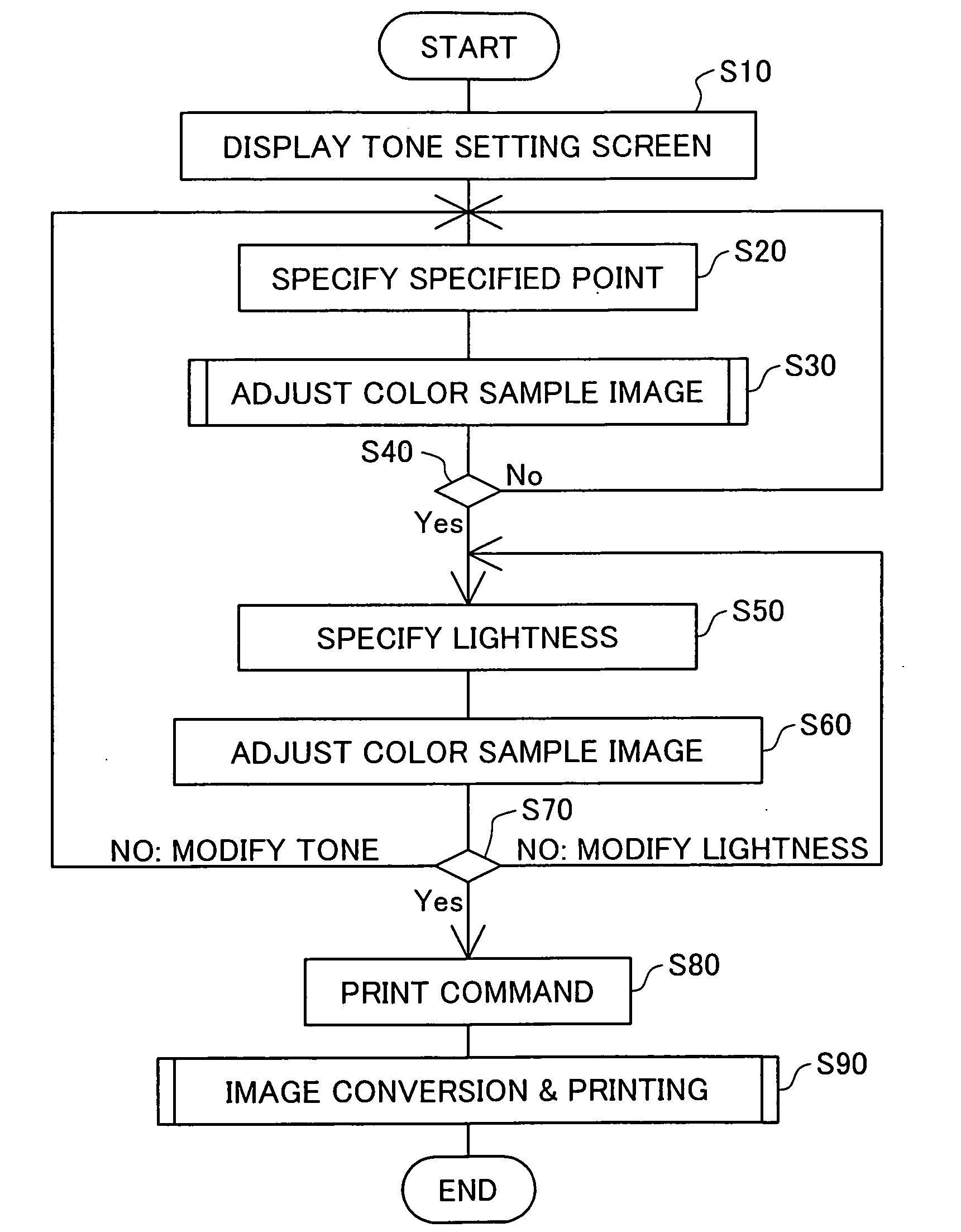
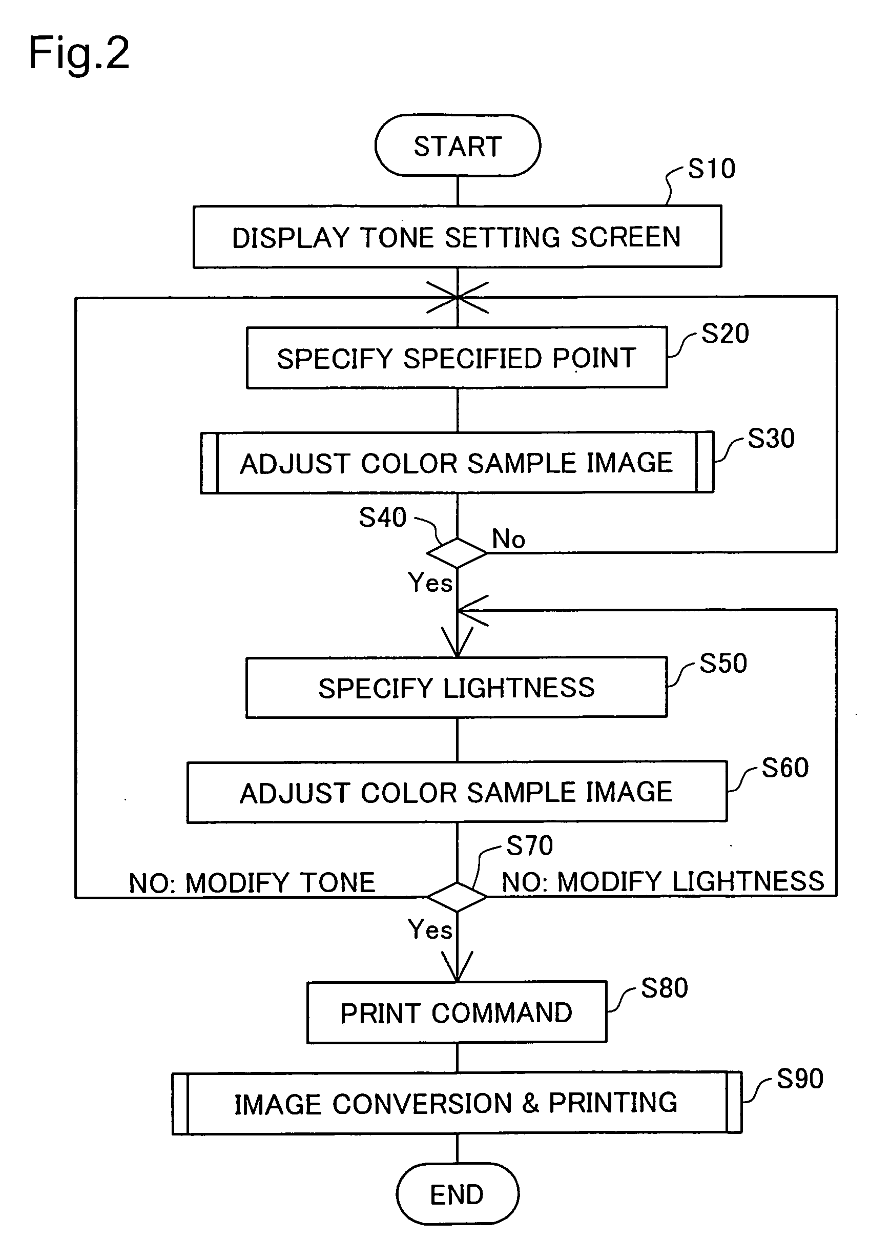
[0115]FIG. 12 is a flowchart showing the procedure of Embodiment 2. In Embodiment 1, tone is specified by specifying a specified point Pcc within the color circle 210 in Step S20 of FIG. 2, and lightness is specified using the lightness scale 230 in Step S50. In Embodiment 2, after specifying lightness in Step S50, contrast adjustment is performed by controlling a contrast scale 240. Other aspects are the same as in Embodiment 1.
[0116] In Embodiment 2, if the user decides in Step S70 that the lightness of the color sample image is acceptable, the process proceeds to Step S100. In Step S100, the user specifies a level of contrast adjustment, through the contrast scale 240 (see FIG. 3).
[0117]FIG. 13 is an illustration showing contrast conversion curves Cc for red tone values. In the contrast conversion process, red tone values for pixels calculated by the process up through Step S50 are converted according to the contrast conversion curves Cc. In FIG. 13, two curves C...
embodiment 3
C. Embodiment 3
[0125] Embodiment 3 differs from Embodiment 1 in terms of the arrangement of the color circle in the tone setting screen 200 (see FIG. 3) and the method for adding a color tone (see FIG. 4). Other aspects are the same as Embodiment 1.
[0126]FIG. 14 is an illustration showing the color circle 213 of Embodiment 3. In Embodiment 3, the color circle 213 is a disk having a gray point at the center, with at least one hue selected from red, green, and blue differing stepwise depending on location within the color circle 213. Of the colors that change stepwise, the outer peripheral portion of the color circle 213 of Embodiment 3 contains the colors of a hue circle. This color circle 213 has, for example, a point Pb at which red=0, blue=100%, and green=0 at the 12-o'clock position on the circumference of the circle, a point Pg at which red=0, blue=0, and green=100% at the 4-o'clock position on the circumference of the circle, and a point Pr at which red=100%, blue=0, and green...
embodiment 4
D. Embodiment 4
[0131] The software of the printing system of Embodiment 4 comprises, instead of the first parameter correspondence table 104e (see FIG. 1 and FIG. 9), a second parameter correspondence table 104f. In Embodiment 4, the arrangement of the color circle (see FIG. 3), the method for determining hue for application to a monochrome image, and the method for generating image data MID2 from image data MID1 are different from those in Embodiment 1. Other aspects are the same as Embodiment 1. Accordingly, the procedure when determining hue to be applied to a monochrome image, adjusting a color sample image, and generating image data MID2 is described hereinbelow.
[0132]FIG. 16 is an illustration showing the relationship of a color circle 214 and a CMY color triangle 215 in Embodiment 4. In Embodiment 4, the color circle is a disk having a gray point at its center, with at least one hue selected from cyan, magenta, and yellow differing stepwise depending on location within the c...
PUM
 Abstract
Description
Claims
Application Information
 - R&D
- Intellectual Property
- Life Sciences
- Materials
- Tech Scout
- Unparalleled Data Quality
- Higher Quality Content
- 60% Fewer Hallucinations
Browse by: Latest US Patents, China's latest patents, Technical Efficacy Thesaurus, Application Domain, Technology Topic, Popular Technical Reports.
© 2025 PatSnap. All rights reserved.Legal|Privacy policy|Modern Slavery Act Transparency Statement|Sitemap|About US| Contact US: help@patsnap.com


