
Methods and Systems for Cooling Hot Particulates

a technology of hot particulates and cooling methods, applied in the direction of lighting and heating apparatus, instruments, fluid pressure control, etc., can solve the problems of large fluidized bed, inability to expand or contract, and difficult to meet the typical cooling requirements of the system

Inactive Publication Date: 2013-11-28
KELLOGG BROWN & ROOT LLC
View PDF12 Cites 13 Cited by
  • Summary
  • Abstract
  • Description
  • Claims
  • Application Information

AI Technical Summary

Benefits of technology

The patent text describes new methods, systems, and apparatus for cooling particulate matter recovered from a gasification process. The technical effect of the patent is to provide more efficient and effective cooling of the particulate matter without causing damage or malfunctions to the gasification process. The new cooling system involves a heat exchanger with a tube bundle containing multiple tubulars that can be expanded or contracted to meet the cooling requirements of the system. The cooling process involves introducing the particulate matter to the heat exchanger and flowing them through the heat exchanger while contacting them with the tubulars. The heated coolant is then recovered and cooled particulate matter is recovered. The new cooling system helps to improve the overall efficiency and reliability of the gasification process.

Problems solved by technology

The removed particulates, however, typically require cooling before being recycled or purged from the system.
This method is not very efficient and only works at low pressures.
A large fluidized bed, however, is not easily expanded or contracted to meet the typical cooling requirements of the system.
And if a portion of the fluidized bed malfunctions, the entire gasification process might have to slow or come to a halt until the fluidized bed cooler can be repaired.
These tubes, however, can succumb to the thermal stresses caused by the high temperatures of the hot particulates.
The tube expansion or contraction can lead to thermal stress causing cracks or other damage to the cooling tubes, which could require a halt to the entire gasification process to repair the cooler.

Method used


Image

  • Methods and Systems for Cooling Hot Particulates
  • Methods and Systems for Cooling Hot Particulates
  • Methods and Systems for Cooling Hot Particulates

Examples


Embodiment Construction

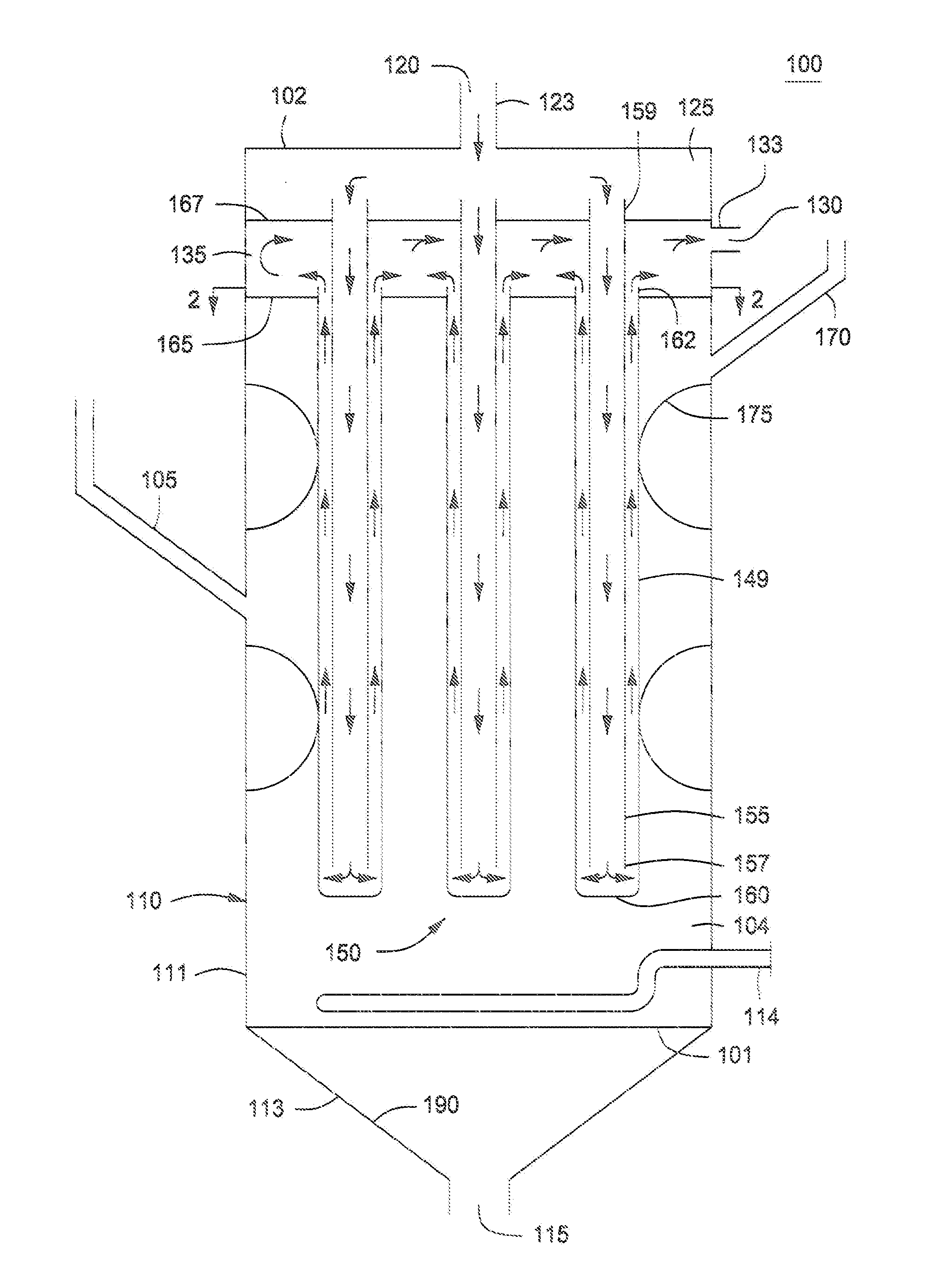
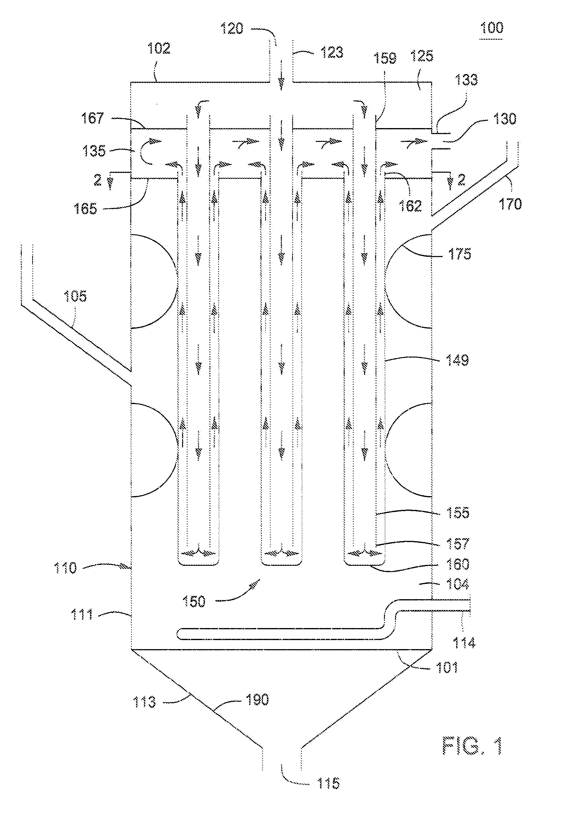
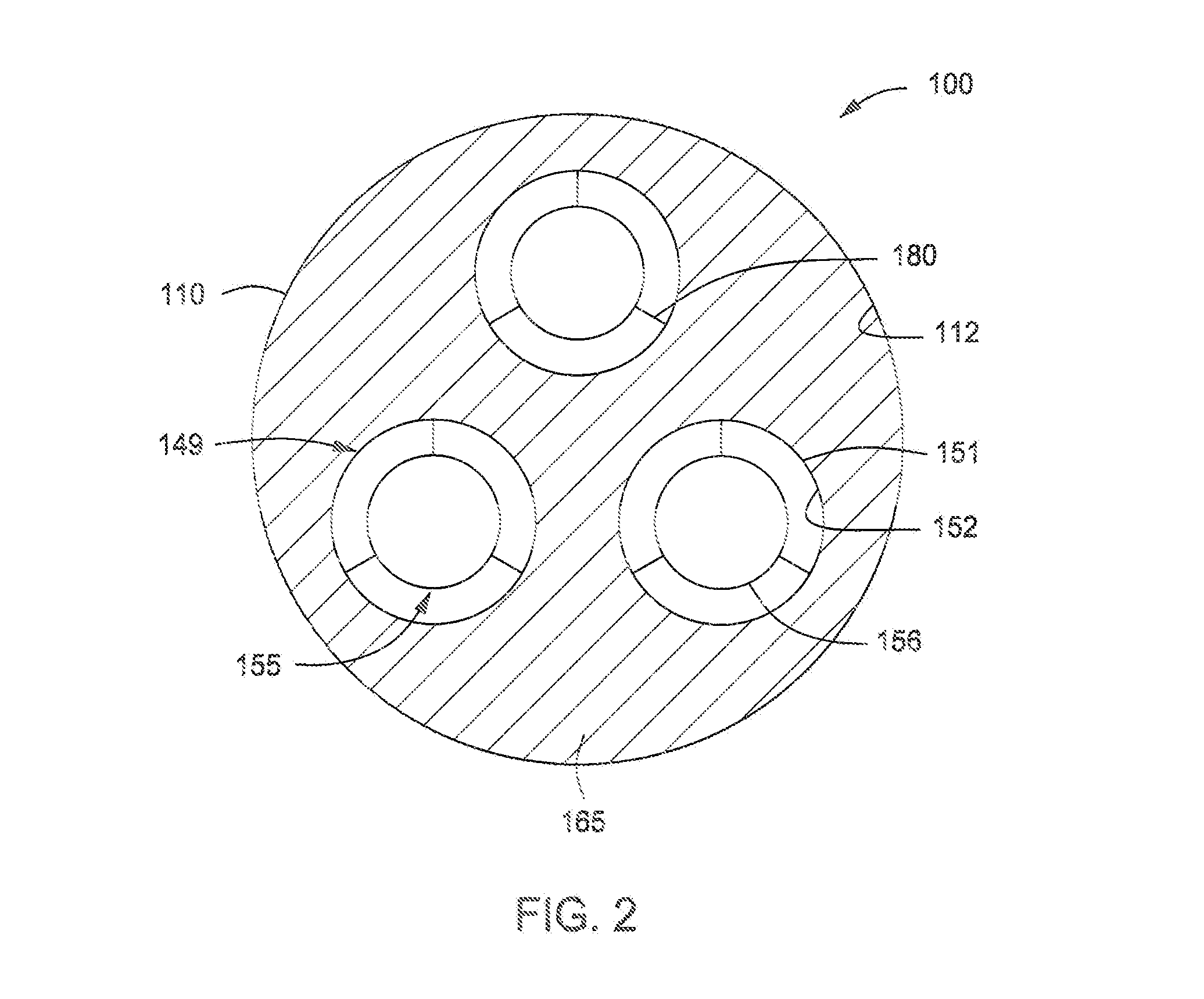
[0014]Methods, systems, and apparatus for cooling particulates are provided. The method for cooling particulates can include introducing particulates to a heat exchanger containing a tube bundle having a plurality of tubulars, introducing a coolant to the plurality of tubulars through a coolant inlet, flowing the particulates through the shell side of the heat exchanger, and contacting at least a portion of the particulates with the tube bundle. The method can also include recovering a heated coolant from the coolant outlet and recovering cooled particulates from the particulate outlet. The heat exchanger can include a vessel having an elongated shell having a first end, a second end, one or more sidewalls, a shell side particulate inlet disposed in the one or more sidewalls for receiving particulates, a shell side particulate outlet disposed adjacent the second end for discharging cooled particulates, and a tube bundle including a plurality of tubulars disposed within the vessel. T...


PUM


Abstract

Methods, systems, and apparatus for cooling particulates are provided. The method can include introducing particulates to a heat exchanger containing a tube bundle having a plurality of tubulars, introducing a coolant to the plurality of tubulars through a coolant inlet, flowing the particulates through the shell side of the heat exchanger, and contacting at least a portion of the particulates with the tube bundle. The method can also include recovering a heated coolant from the coolant outlet and recovering cooled particulates from the particulate outlet. The heat exchanger can include a vessel having an elongated shell having a first end, a second end, one or more sidewalls, a shell side particulate inlet disposed in the one or more sidewalls for receiving particulates, a shell side particulate outlet disposed adjacent the second end for discharging cooled particulates, and a tube bundle including a plurality of tubulars disposed within the vessel.

Description

BACKGROUND[0001]1. Field[0002]Embodiments described herein generally relate to the gasification of hydrocarbons. More particularly, such embodiments relate to cooling particulates recovered from a gasification process.[0003]2. Description of the Related Art[0004]Raw synthesis gas leaving a gasifier can contain particulates such as coarse ash, fine ash, and / or slag that need to be removed prior to further processing. The bulk of the particulates can be removed using a particulate removal system such as filters and / or cyclones. The removed particulates are typically recycled to the gasifier or purged from the system as a byproduct, and the syngas leaving the particulate removal system is further processed and / or purified. The removed particulates, however, typically require cooling before being recycled or purged from the system.[0005]One method for cooling the removed particulates is to drop the hot particulates into a vessel of water and the cooled particulates are then separated fr...

Claims


Application Information

Patent Timeline
Patent Type & Authority Applications(United States)
IPC IPC(8): F28D15/00F28F27/02G05D16/00
CPCF28D1/02F28D7/0041F28D7/12F28D13/00G05D16/00C10J3/56Y02P20/129C10J3/00C10J2300/1628F28D7/005F28D7/06F28D7/1607F28F9/0202
Inventor CHAN, IWAN H.PHILLIPS, WILLIAM E,LI, YONGCHAO
Owner KELLOGG BROWN & ROOT LLC
Learn More