Home appliance with support assembly

a technology for home appliances and support legs, which is applied in the field of floor-standing home appliances, can solve the problems of high concentration, damage to the floor, and difficulty in using threaded cylinders, such as bolts, for supporting legs, and achieve the effect of range heigh

Active Publication Date: 2013-11-28
BSH HOME APPLIANCES CORP
View PDF2 Cites 15 Cited by
  • Summary
  • Abstract
  • Description
  • Claims
  • Application Information

AI Technical Summary

Benefits of technology

[0007]It is another object to the present invention to provide such a leg support assembly that will distribute the weight of the range effectively.
[0009]Preferably, the support member is a threaded cylinder threadedly attached to the appliance body whereby rotation of the support member changes the distance of the appliance body from the support surface and thereby the overall height of the appliance.
[0016]It is preferred that the support member is a threaded cylinder threadedly attached to the range body whereby rotation of the support member changes the distance of the range body from the support surface and thereby the overall height of the range.

Problems solved by technology

Such weight concentration, on the average of one hundred twenty five (125) pounds per corner, presuming even distribution of weight, can cause difficulties for using threaded cylinders, such as bolts, for support legs.
However, the bolt head presents a small footprint and therefore a high concentration of weight in the form of pressure on the support surface, usually a kitchen floor, which can be damaging to the floor.
Such custom leg structures can be unnecessarily expensive to manufacture and use.

Method used


Image

  • Home appliance with support assembly
  • Home appliance with support assembly
  • Home appliance with support assembly

Examples


Embodiment Construction

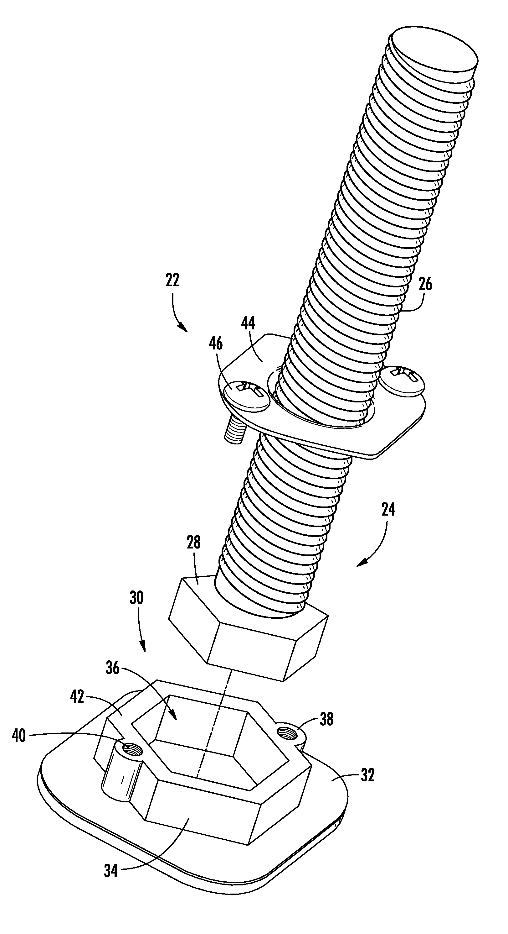
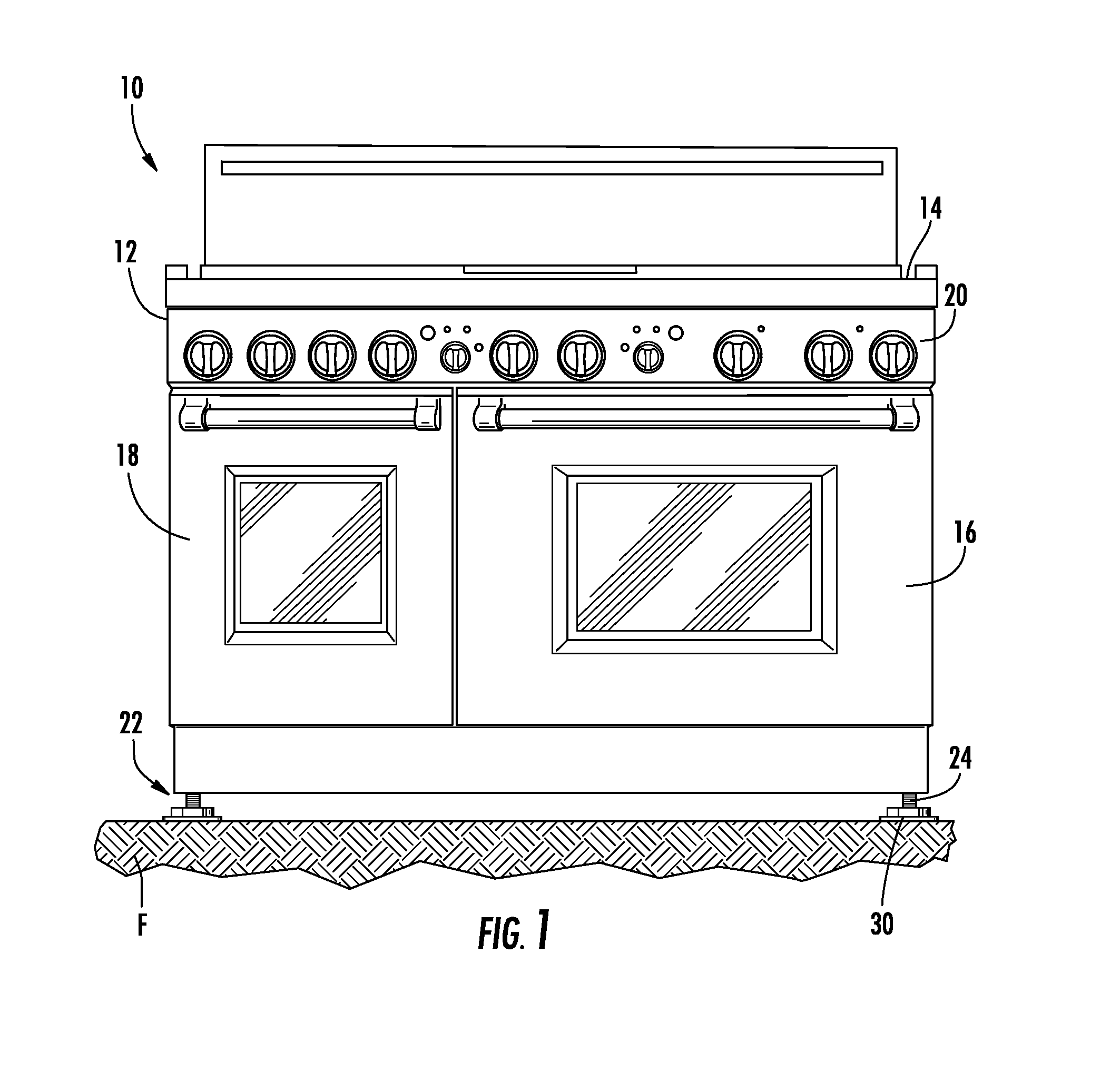
[0028]Turning now to the drawings and, more particularly to FIG. 1, a home appliance in the nature of a range is illustrated generally at 10 includes a generally box-like, floor standing range body 12 with a cooktop 14 mounted to the upper portion of the range body 12. The central portion of the range body 12 defines an oven and a combination steamer and convection oven (not shown). The oven and combination steamer / convection oven are covered by doors illustrated at 16 and 18 respectively. A control panel 20 is located intermediate the cooktop 14 and the doors 16, 18. The range body 12 is supported on a support surface such as a floor F by the present support assembly 22. It should be noted that the support assembly 22 is shown in FIG. 1 with a somewhat exaggerated size for clarity. The support assembly 22 includes two primary components. These include a generally cylindrical, threaded support leg 24 and a shoe 30 fitted to the support leg 24.

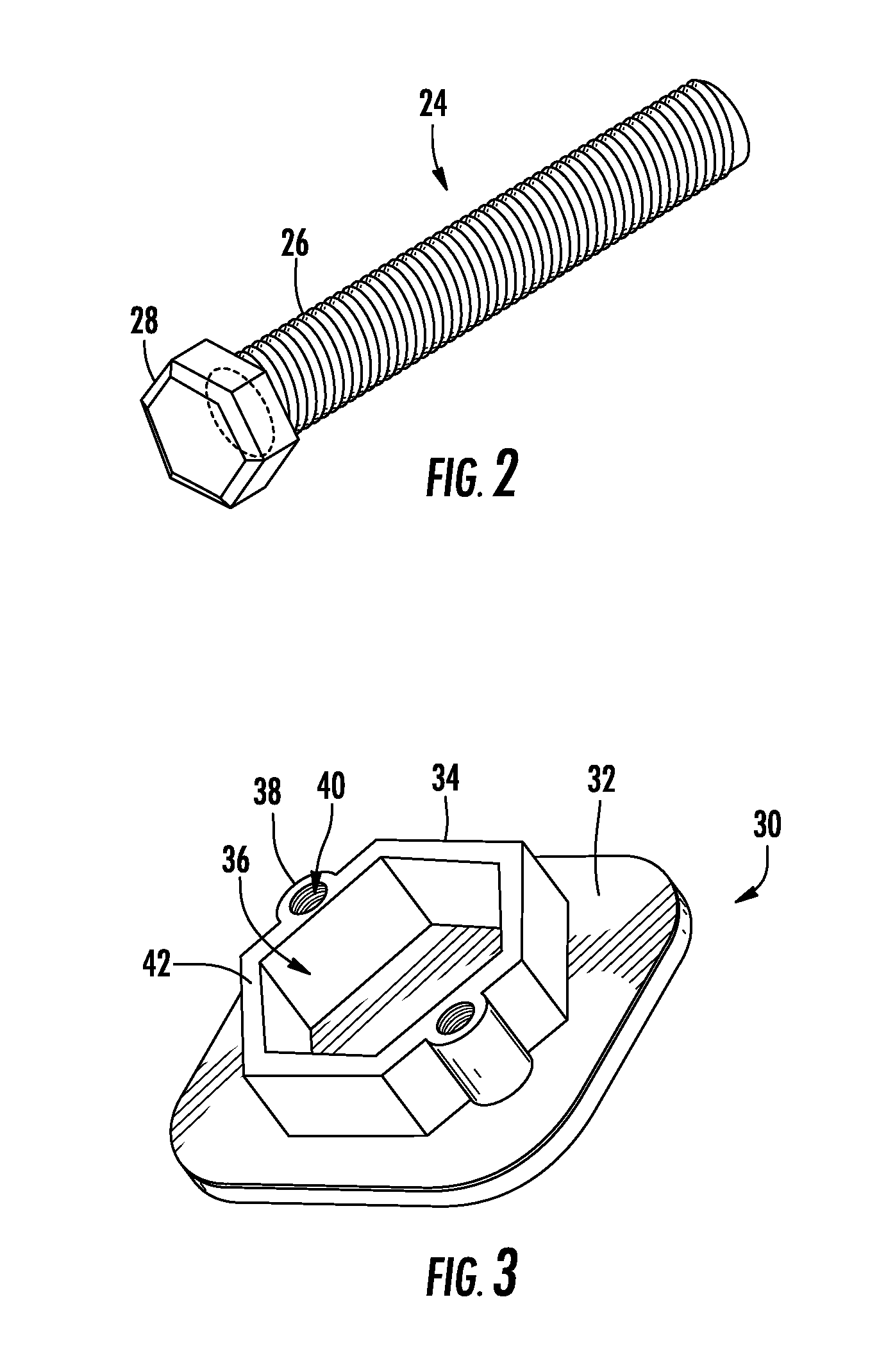
[0029]Turning now to FIG. 2, the support...


PUM


Abstract

A floor-standing home appliance in the nature of a range including an appliance body and a support assembly for supporting the appliance body on a support surface, the support assembly including a support member extending away from the appliance body, the support member having an engagement member with a predetermined shape at a distal end thereof, and a shoe attached to the distal end of the support member, the shoe having a receiving well with a shape complimentary to the predetermined shape of the engagement member to receive the engagement member in the receiving well.

Description

BACKGROUND OF THE INVENTION[0001]The present invention relates broadly to floor-standing home appliances and, more particularly, to a home appliance, in the nature of a range, having a two-piece support assembly.[0002]Ranges are generally box-like, floor-standing appliances that include some form of leg support mounted at four corners of the range body. In whatever form, such support should be adjustable so that the height of the range can be varied for appearance and leveling purposes. To that end, some ranges include threaded apertures in the range frame for receiving threaded cylinders that can support the range on a floor and may be rotated in and out of the apertures to adjust the height of the range.[0003]Some ranges are also relatively heavy, weighing more than five hundred (500) pounds. Such weight concentration, on the average of one hundred twenty five (125) pounds per corner, presuming even distribution of weight, can cause difficulties for using threaded cylinders, such ...

Claims


Application Information

Patent Timeline
Patent Type & Authority Applications(United States)
IPC IPC(8): A47B91/02A47B91/00
CPCF24C15/086
Inventor ADAMS, DAVIDRUTHERFORD, MICHAEL
Owner BSH HOME APPLIANCES CORP
Why Eureka
Try Eureka