

Antenna structure
- Summary
- Abstract
- Description
- Claims
- Application Information
AI Technical Summary
Benefits of technology
Problems solved by technology
Method used
Image

Examples
first embodiment
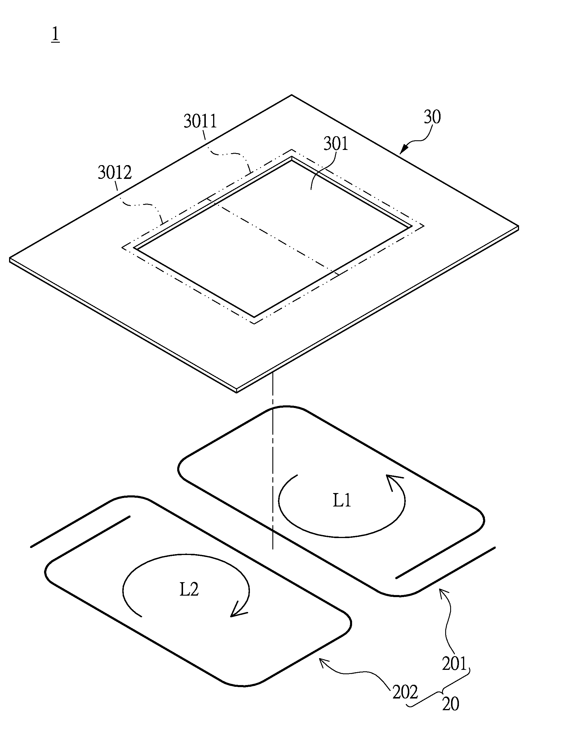
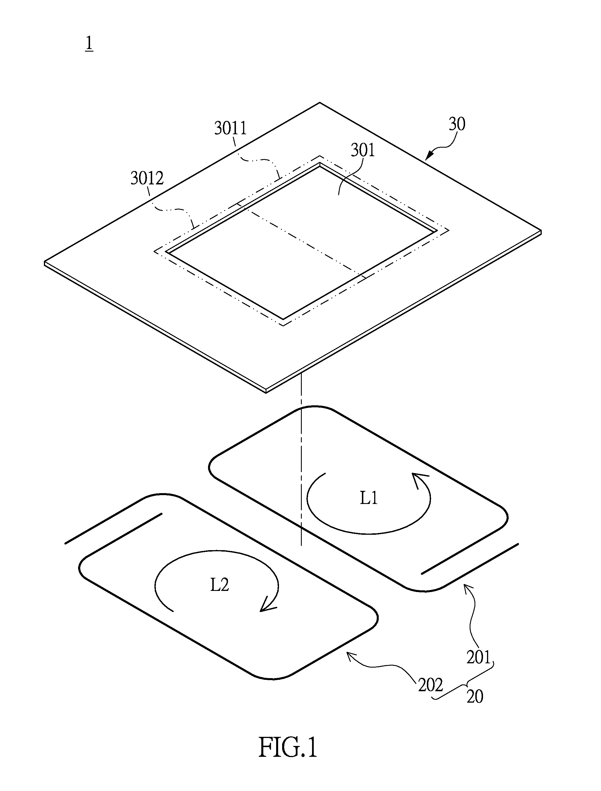
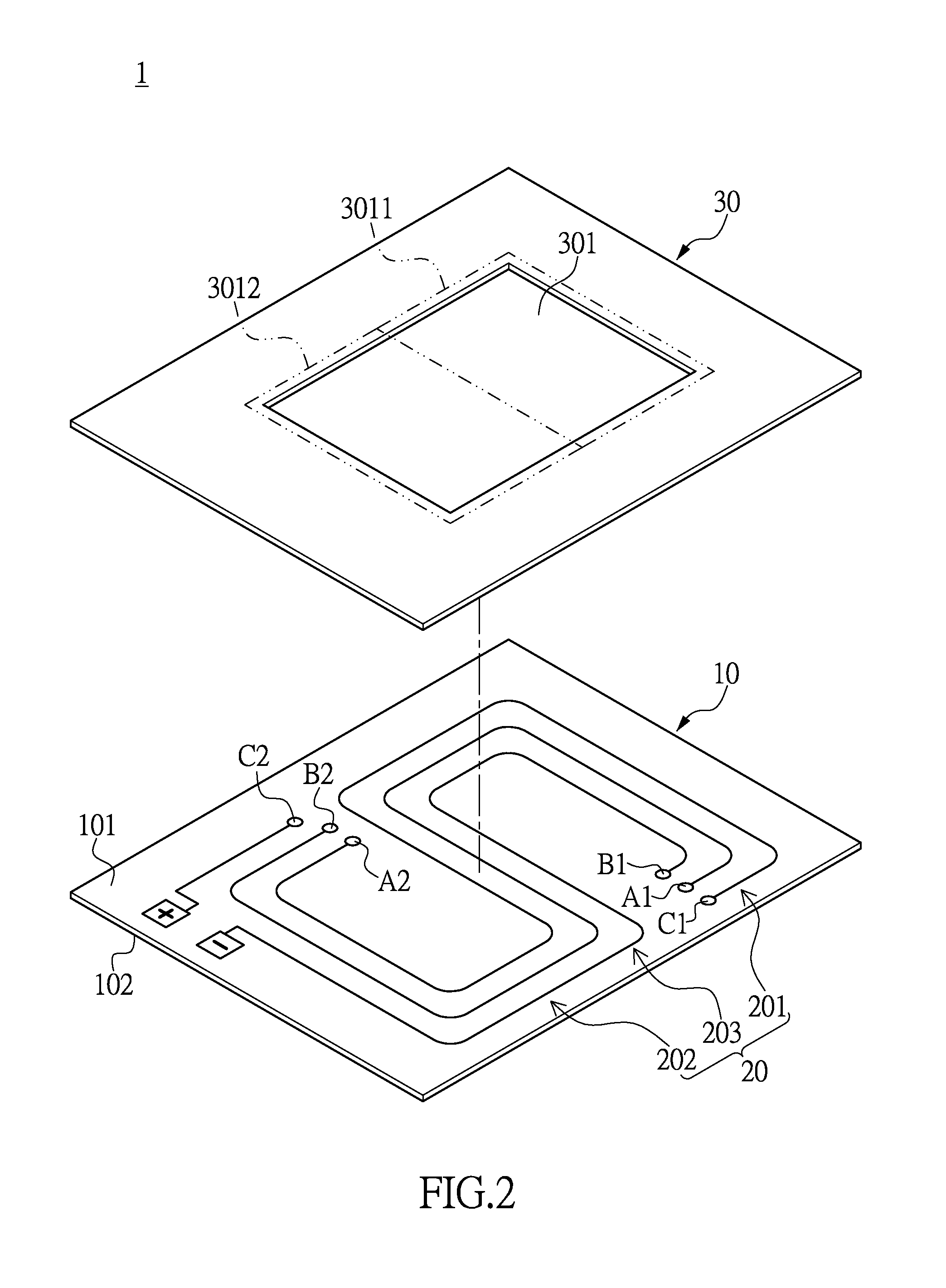
[0026]FIG. 2 shows a first schematic diagram of an antenna structure according to the first embodiment of the present disclosure. The antenna structure 1 includes: an insulation carrier board 10, a radiation module 20 and a metal board 30. The radiation module 20 is disposed on the insulation carrier board 10. The metal board 30 is disposed on top of the insulation carrier board 10. The radiation module 20 includes: a first coil unit 201, a second coil unit 202 and a connection unit 203. The first coil unit 201 and the second coil unit 202 are coupled. The first coil unit 201 and the second coil unit 202 are disposed on the first surface 101 of the insulation carrier board 10. The connection unit 203 connects the first coil unit 201 and the second coil unit 202. In a preferred embodiment, the second coil unit 202, as shown in the figure, is connected to the positive terminal and the negative terminal of the first surface 101 of the insulation carrier board 10, and through the connec...
second embodiment
[0029]FIG. 4 shows a schematic diagram of a metal board of an antenna structure according to the second embodiment of the present disclosure. Regarding the relative configuration of and connection between the components of the antenna structure 1, please refer to the previous embodiment. Particular to the present embodiment, the enclosed slot 301 of the metal board 30 can be, besides the single rectangular slot of the first embodiment, formed by a plurality of rectangular slots as shown in FIG. 3. Namely, the first slot portion 3011′ and the second slot portion 3012′ are connected through a connection portion 3013. Specifically, in the present embodiment, only the first coil opening 2011 can be seen through the first slot portion 3011′, and only the second coil opening 2021 can be seen through the second slot portion 3012′. In other words, from a top view, the connection unit 203 can be seen only through the connection portion 3013 of the enclosed slot 301, and no wiring is visible ...
third embodiment
[0030]FIG. 5 shows a schematic diagram of an antenna structure according to the third embodiment of the present disclosure. As mentioned in the above embodiment, the antenna structure 1 includes: an insulation carrier board 10, a radiation module 20 and a metal board 30, the respective connection and configuration of which are similar to those of the previous embodiment. Particular to the present embodiment, the first coil unit 201 and the second coil unit 202 of the radiation module 20 have the form shown in FIG. 5. Specifically, the first surface 101 of the insulation carrier board 10 has a positive terminal N1, a negative terminal N2, a first connection terminal C1 and a second connection terminal C2. The first connection terminal C1 and the second connection terminal C2 are connected through a connection unit 203 on the second surface 102 of the insulation carrier board 10. The two ends of the first coil unit 201 respectively connect to the positive terminal N1 and the first con...
PUM
 Abstract
Description
Claims
Application Information