Digital control servo system

a digital control and servo technology, applied in the field of servo systems, can solve the problems of slow system adaptation to a digital topology and implementations that still do not provide sufficient resolution, and achieve the effect of great effective resolution and dynamic range of optical scanner operation

Inactive Publication Date: 2007-04-03
GSI LUMONICS CORP +1
View PDF136 Cites 11 Cited by
  • Summary
  • Abstract
  • Description
  • Claims
  • Application Information

AI Technical Summary

Benefits of technology

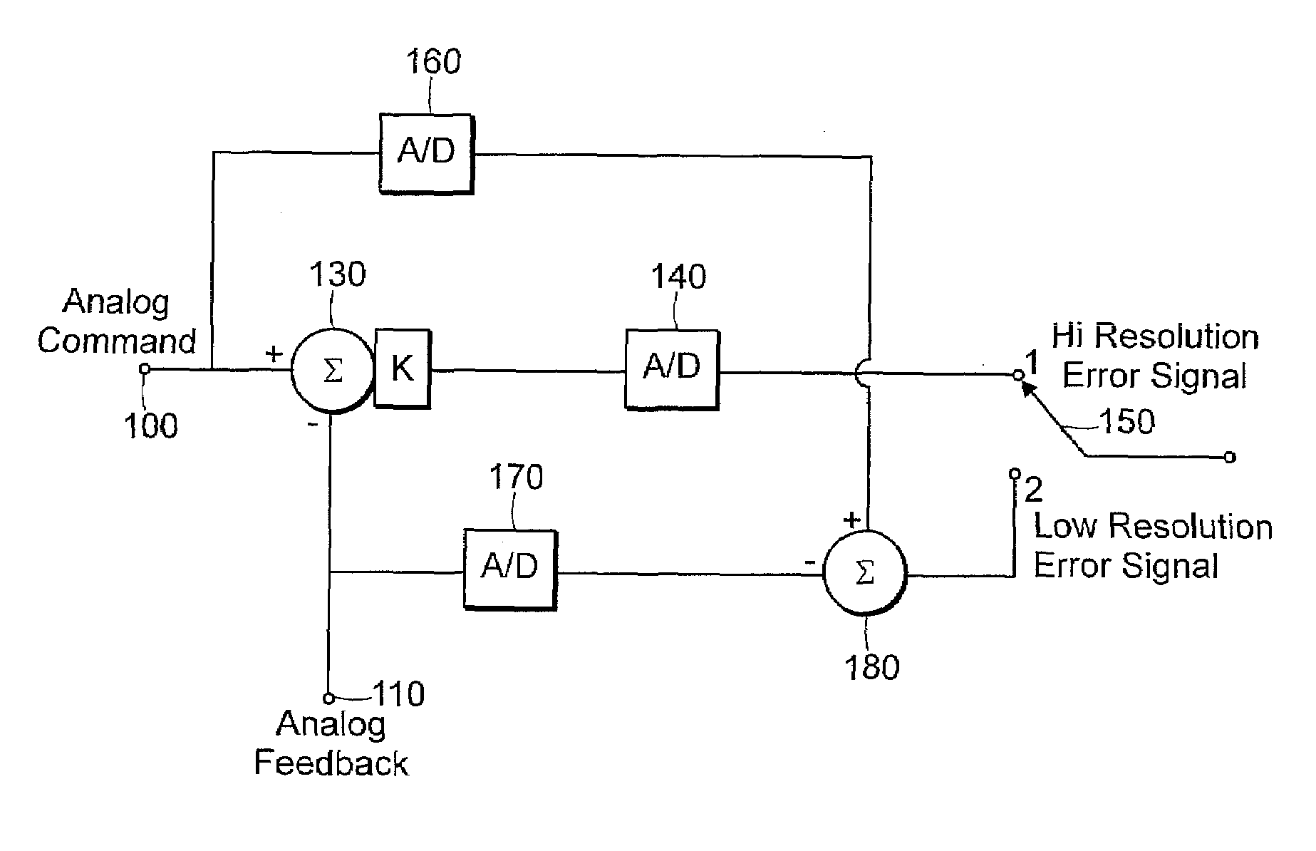
[0011]Accordingly, an object of the present invention is to provide a servo system that allows digital processing techniques to work with appropriate analog command and position feedback signals to provide a greater effective resolution and dynamic range of optical scanner operation.

Problems solved by technology

These systems were slow to adapt to a digital topology because of the ruggedness and proven reliability of the existing designs.
However, many of these implementations still do not provide sufficient resolution during the entire servo process.

Method used


Image

  • Digital control servo system
  • Digital control servo system
  • Digital control servo system

Examples


Embodiment Construction

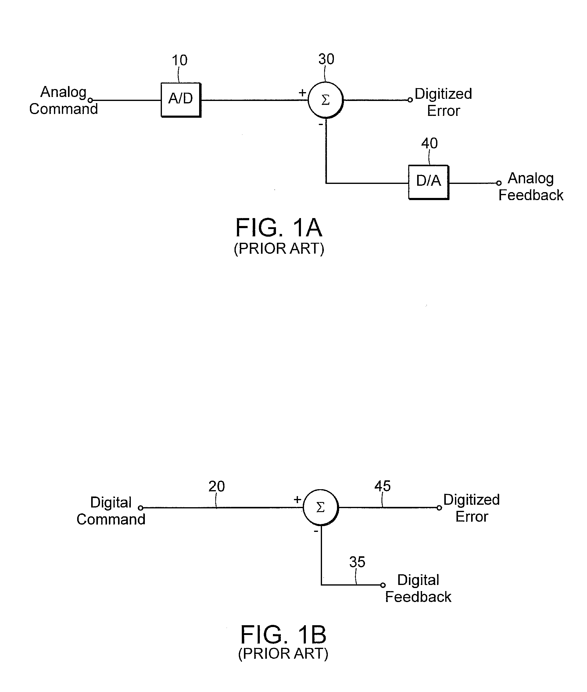
[0039]The invention is susceptible of many embodiments, including the following preferred embodiments. The description includes reference to prior art practices for context. FIGS. 1A and 1B depict prior art servo feedback system elements. There are basically two forms of existing servo feedback architectures, an analog system in the form of a resolver and a digital feedback system in the form of an encoder. FIG. 1A is an analog position feedback servo system element, where the analog command and position feedback signals are separately digitized by A / D converters 10 and 40. The error is then the arithmetic sum of these two digitized values as represented by summation symbol 30, the function being performed by the system processor. FIG. 1B illustrates the digital feedback servo system element where a digital command 20 and a digital position feedback signal 35 are summed to produce a resultant digitized error signal 45.

[0040]Referring now to FIG. 2, preferred embodiment of the invent...


PUM

PropertyMeasurementUnit
temperatureaaaaaaaaaa
galvanometer optical scanningaaaaaaaaaa
frequencyaaaaaaaaaa

Abstract

An improved servo system for galvanometers, scanners and similar devices which uses digital processing to increase the dynamic range and provide greater effective resolution. The system provides digital control of a reference point that directly influences the excitation, which in turn directly influences the gain of the circuit. A high and low resolution switching path is provided to optimize dynamic range. Wide angle torque compensation improves uniformity of response at large angular deflections from zero. Improved thermal protection allows safe operation near system thermal limits. A graphical user interface allows adjustments and changes response on the fly for tuning due to input conditions or user control.

Description

[0001]This application relates and claims priority for all purposes to pending U.S. provisional application Ser. No. 60 / 234,405, filed Sep. 21, 2000.TECHNICAL FIELD OF THE INVENTION[0002]The present invention relates to an improved servo system for an optical scanning device, and more specifically, to a servo system for optical scanning systems that incorporates digital servo control with an on-board processor and a graphical user interface (GUI) setup tool.BACKGROUND OF THE INVENTION[0003]A servo system is a control system that causes some output variable(s) to track some input variable(s). Traditional servo systems have employed analog servo circuits and processing techniques. These systems often use a “PID” (Proportional Integrator Derivative) control algorithm where an error signal contributes to subsequent control signals.[0004]As digital sensors and processing techniques have become more common and cost-effective, many analog servo circuits have been replaced by digital implem...

Claims


Application Information

Patent Timeline
Patent Type & Authority Patents(United States)
IPC IPC(8): G05B19/29G05B11/01G05B19/042G06K7/10G11B
CPCG06K7/10851G06K7/14
Inventor NUSSBAUM, MICHAEL BSHANNON, MICHAEL RSTEWART, FREDRICK A
Owner GSI LUMONICS CORP
Why Eureka
Try Eureka