Digital control servo system

a digital control and servo technology, applied in the field of servo systems, can solve the problems of slow system adaptation to a digital topology and implementations that still do not provide sufficient resolution, and achieve the effect of great effective resolution and dynamic range of optical scanner operation

Inactive Publication Date: 2007-10-11
THE GSI GRP LLC
View PDF48 Cites 12 Cited by
  • Summary
  • Abstract
  • Description
  • Claims
  • Application Information

AI Technical Summary

Benefits of technology

[0011] Accordingly, an object of the present invention is to provide a servo system that allows digital processing techniques to work with appropriate analog command and position feedback signals to provide a greater effective resolution and dynamic range of optical scanner operation.
[0012] A further object of the invention is the digitizing of an analog error signal in addition to separately digitized command and position feedback signals. In particular, the present invention employs a dual resolution scheme. A high-resolution path is available for low error conditions, while a low-resolution system can be used for higher error conditions. This provides greater effective resolution and dynamic range.
[0014] An additional object is real-time, on-line tuning of the servo system operating algorithm and parameters described above. A graphical user interface (GUI) with simulated analog presentations and inputs is used to provide a simple operator interface tool to measure and alter system parameters through an on-board digital processor.
[0017] Yet another object of the invention is to provide a real-time scanner capacity to monitor rotor magnet thermal margins by calculating peak coil temperatures from scanner current and thermal parameters, and combining this information with baseline temperature readings from a sensor located in the scanner. The on-board sensor and thermal model of current allows continual operation of the device close to the thermal limits of the scanner by accounting for both ambient temperature and coil current heating.

Problems solved by technology

These systems were slow to adapt to a digital topology because of the ruggedness and proven reliability of the existing designs.
However, many of these implementations still do not provide sufficient resolution during the entire servo process.

Method used


Image

  • Digital control servo system
  • Digital control servo system
  • Digital control servo system

Examples


Embodiment Construction

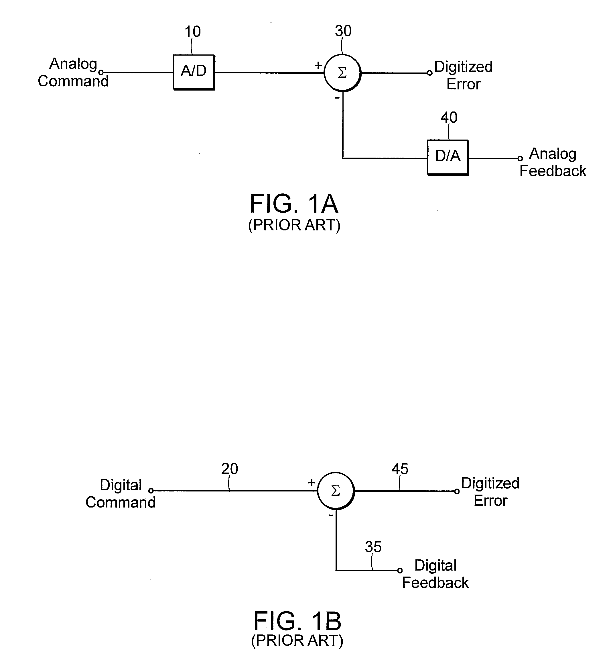
[0039] The invention is susceptible of many embodiments, including the following preferred embodiments. The description includes reference to prior art practices for context. FIGS. 1A and 1B depict prior art servo feedback system elements. There are basically two forms of existing servo feedback architectures, an analog system in the form of a resolver and a digital feedback system in the form of an encoder. FIG. 1A is an analog position feedback servo system element, where the analog command and position feedback signals are separately digitized by A / D converters 10 and 30. The error is then the arithmetic sum of these two digitized values as represented by summation symbol 30, the function being performed by the system processor. FIG. 1B illustrates the digital feedback servo system element where a digital command 20 and a digital position feedback signal 35 are summed to produce a resultant digitized error signal 45.

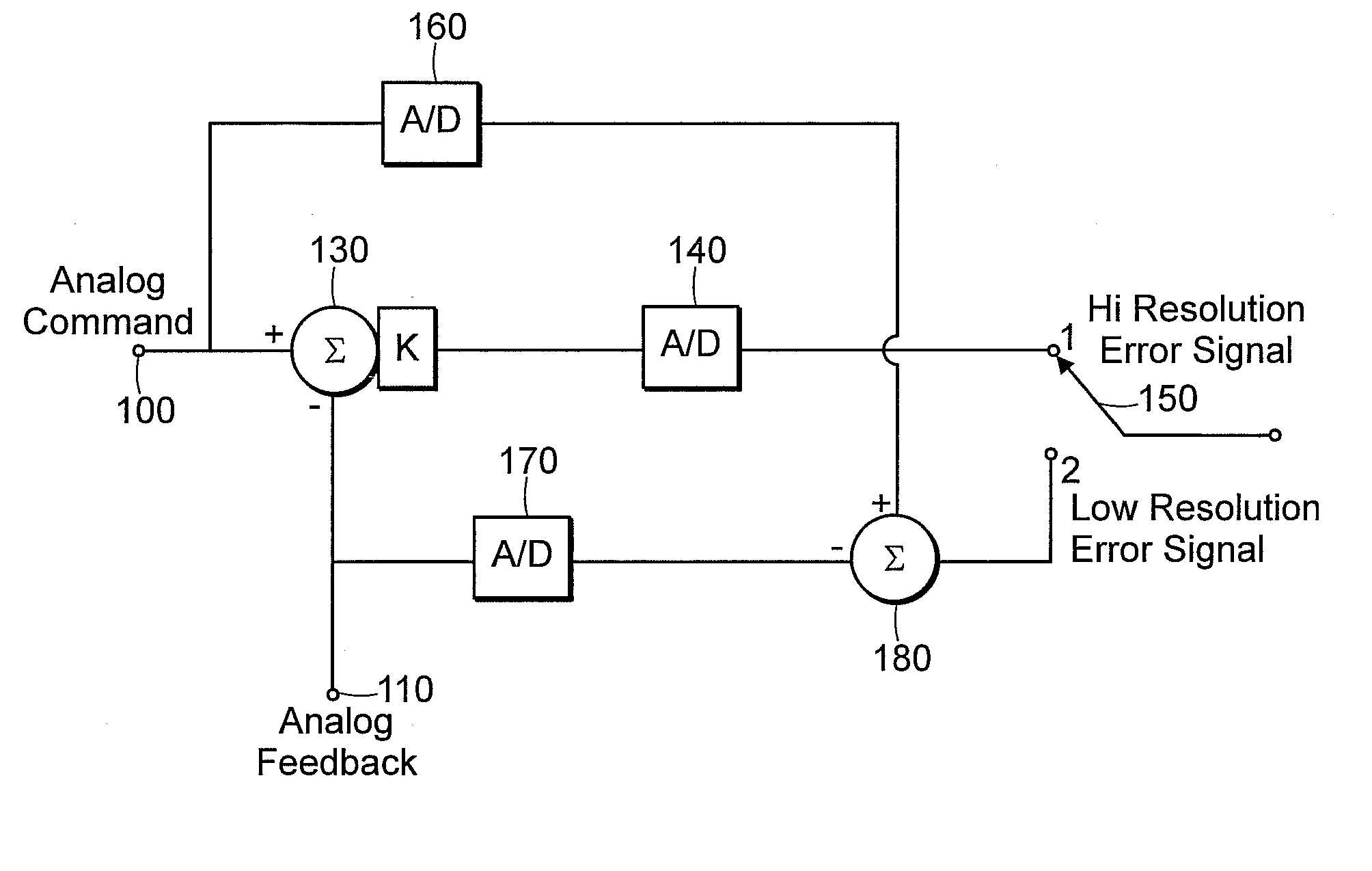
[0040] Referring now to FIG. 2, a preferred embodiment of the i...


PUM

PropertyMeasurementUnit
temperatureaaaaaaaaaa
torqueaaaaaaaaaa
real-timeaaaaaaaaaa

Abstract

A limited rotation motor optical scanning system is disclosed that includes a limited rotation motor scanner, a digital controller servo system, a position feedback unit, a wide angle compensation unit, a digital processor, and an adjustment unit. The limited rotation motor scanner element is adapted for directing an energy beam to at least one location within a field of view. The digital controlled servo system is adapted for controlling motion of the limited rotation motor scanner element in accordance with a servo command waveform. The position feedback unit is for providing a position feedback signal indicative of a rotational position of the limited rotation motor scanner element. The wide angle compensation unit is for receiving the position feedback signal and for providing a boost signal that is representative of a boost factor that compensates for torque constant variation with the rotational position of said limited rotation motor scanner element. The digital processor is for providing a set of control parameters for use during the command waveform in conformance with which the command waveform will be employed to control motion of the limited rotation motor scanner element. The adjustment unit is for providing an adjusted output signal responsive to the control parameters and responsive to the boost signal to control the motion of the limited rotation motor scanner element while compensating for torque constant variation with the rotational position of the limited rotation motor scanner element during the command waveform.

Description

PRIORITY [0001] This application is a continuation application of U.S. patent application Ser. No. 09 / 957,788 which was filed on Sep. 21, 2001, which relates and claims priority for all purposes to pending U.S. provisional application Ser. No. 60 / 234,405, filed Sep. 21, 2000.TECHNICAL FIELD OF THE INVENTION [0002] The present invention relates to an improved servo system for an optical scanning device, and more specifically, to a servo system for optical scanning systems that incorporates digital servo control with an on-board processor and a graphical user interface (GUI) setup tool. BACKGROUND OF THE INVENTION [0003] A servo system is a control system that causes some output variable(s) to track some input variable(s). Traditional servo systems have employed analog servo circuits and processing techniques. These systems often use a “PID” (Proportional Integrator Derivative) control algorithm where an error signal contributes to subsequent control signals. [0004] As digital sensors...

Claims


Application Information

Patent Timeline
Patent Type & Authority Applications(United States)
IPC IPC(8): G06F19/00G05B19/29G05B11/01G05B19/042G06K7/10G11B
CPCG06K7/10851G06K7/14
Inventor NUSSBAUM, MICHAEL B.SHANNON, MICHAEL R.STEWART, FREDERICK A.
Owner THE GSI GRP LLC
Why Eureka
Try Eureka