Capacitor hybrid fuel cell power generator

a hybrid fuel cell and capacitor technology, applied in the field of electric power generation, can solve the problems of increasing wear and tear on the fuel cell system components, reducing system operating life, and difficulty in precisely determining when and how much the battery needs to be charged by the fuel cell stack, so as to prolong the life of the fuel cell, reduce the stress on the fuel cell, and reduce the effect of fuel cell stress

Inactive Publication Date: 2007-04-19
GENERAL HYDROGEN CORP
View PDF99 Cites 9 Cited by
  • Summary
  • Abstract
  • Description
  • Claims
  • Application Information

AI Technical Summary

Benefits of technology

[0010] According to one aspect of the invention, there is provided a method of operating an electrical power generator comprising at least one fuel cell and at least one capacitor electrically coupled together in parallel. The method comprises: monitoring a current drawn by a load; monitoring a voltage across the capacitor, and operating the fuel cell to generate an electrical output within a target output range when either the monitored current or voltage are within a respective selected current and voltage range, the fuel cell output supplying the load and / or recharging the capacitor. The capacitor is configured to discharge stored electrical energy to the load when the load exceeds the target output range. Operating the generator using such a method enables the fuel cell to operate within an efficient range that reduces stress on the fuel cell, thereby prolonging the life of the fuel cell.
[0012] When the monitored current is below the current range and the monitored voltage is within the voltage range, the load is below the target output range of the fuel cell and the capacitor requires recharging. In such case, the recharging rate of the capacitor can be reduced by reducing the fuel cell output. This prolongs fuel cell power generation and reduces the frequency of starting and stopping the fuel cell, thereby reducing stress on the fuel cell.
[0013] Particularly, the fuel cell output can be reduced to a lower limit of the target output range to reduce the recharging rate of the capacitor to a minimum. When the monitored voltage reaches an upper limit of the voltage range, the fuel cell operation is stopped. The upper limit of the voltage range can be selected to correspond to a fully charged capacitor. Stopping fuel cell operation can comprise reducing the fuel cell output to zero as the monitored voltage approaches the upper limit of the voltage range. To further prolong fuel cell power generation, the fuel cell output rate is can be further reduced as the monitored voltage approaches the upper limit of the voltage range. Alternatively, stopping fuel cell operation can comprise directing the fuel cell output from recharging the capacitor to heating the fuel cell when the fuel cell output has not reached zero after the monitored voltage reaches the upper limit of the voltage range.
[0015] Additionally, the temperature of the fuel cell can be monitored, and the fuel cell can be operated to generate an electrical output within the target output range when the monitored temperature falls below a selected setpoint. This operation keeps the fuel cell sufficiently warm so that the fuel cell can be quickly started. Starting the fuel cell to generate electrical output can comprise transmitting fuel and oxidant to the fuel cell using power supplied by the capacitor. Once the fuel cell is generating sufficient power, fuel and oxidant transmission can be powered by the fuel cell.

Problems solved by technology

However, load following tends to impose stresses on the fuel cell system, thereby increasing wear and tear on the fuel cell system components and decreasing system operating life.
One of the most significant challenges is determining the state of charge of the battery.
Typically, the battery's state is determined by measuring the current draw on the battery; however this approach does not provide a precise measurement of the banery's charge state, and therefore, it is difficult to precisely determine when and how much the battery needs to be charged by the fuel cell stack.
Furthermore, electrochemical batteries do not have a particularly fast discharge rate, and thus sometimes may be not be able to meet the power demands by the load.
Another disadvantage of using a battery in such a hybrid configuration is that the battery has a relatively slow recharge rate, and thus may not be able to be recharged quickly to supply power to rapidly variable loads.

Method used


Image

  • Capacitor hybrid fuel cell power generator
  • Capacitor hybrid fuel cell power generator
  • Capacitor hybrid fuel cell power generator

Examples


Embodiment Construction

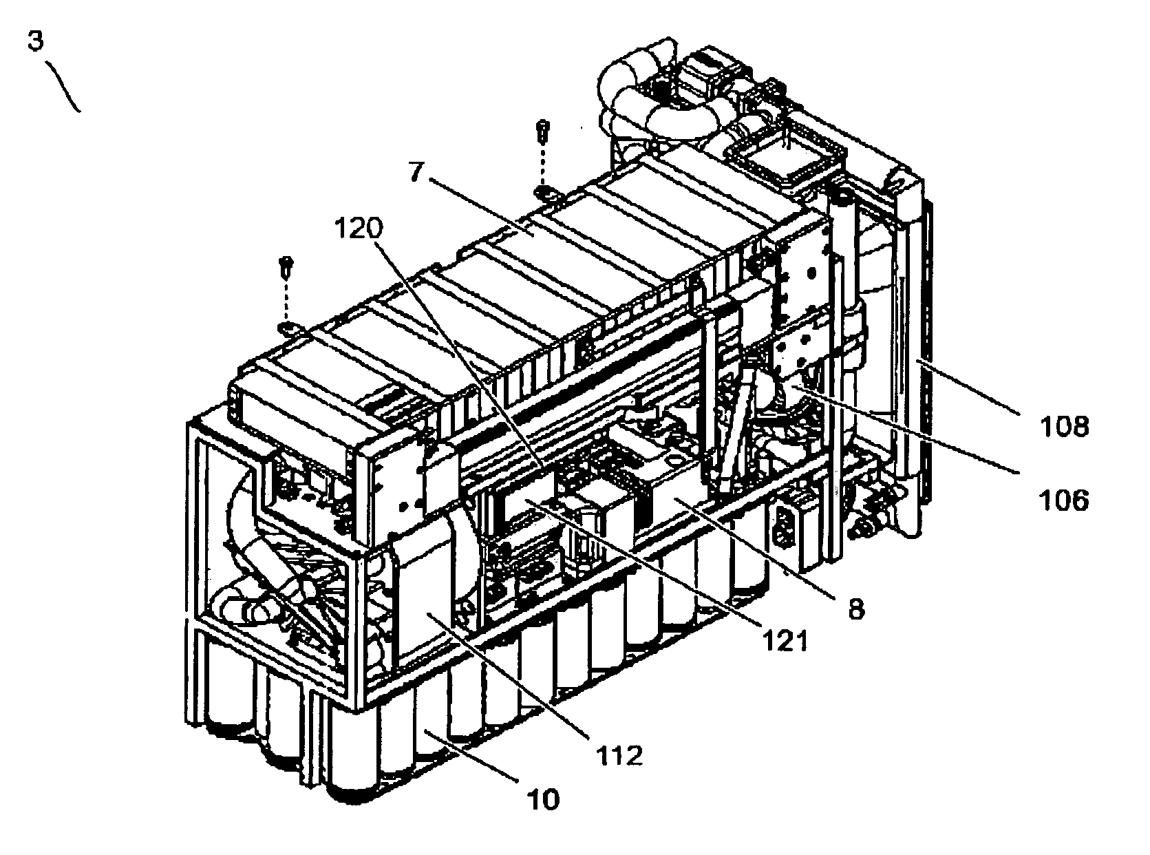
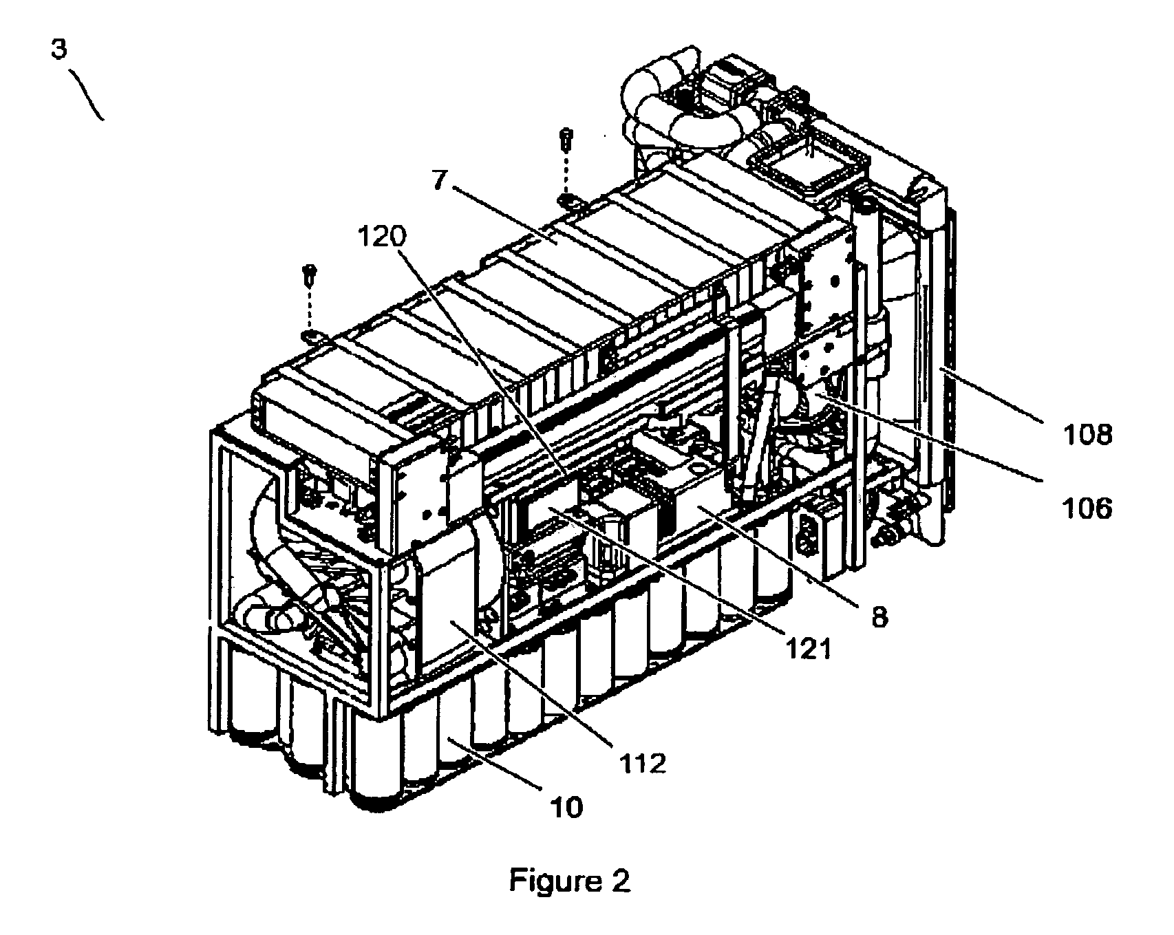
[0028] Referring to FIG. 2 and according to one embodiment of the invention, an electrical power generator 3 is provided which comprises a fuel cell stack 7 and a double-layer capacitor bank 10 electrically coupled in parallel. The fuel cell stack 7 electrochemically reacts gaseous hydrogen fuel supplied from a fuel tank (not shown) and oxygen from ambient air to produce electricity. By-products of the reaction include water and heat. The fuel cell stack 7 comprises a plurality of a proton exchange member (PEM) type fuel cells; a suitable such fuel cell stack is the Mark 902 stack manufactured by Ballard Power Systems. However, it is within the scope of the invention to use other fuel stacks as is known in the art. The capacitor bank 10 is made up of a plurality of double-layer capacitors connected in series to provide a capacitor voltage sufficient to meet the voltage requirements of a load, and each series-connect double-layer capacitor may consist of group of parallel connected d...


PUM

PropertyMeasurementUnit
voltageaaaaaaaaaa
voltageaaaaaaaaaa
currentaaaaaaaaaa

Abstract

An electrical power generator comprising at least one fuel cell and at least one capacitor electrically coupled together in parallel is operated in a manner that reduces stress on the fuel cell and prolongs fuel cell operating life. The operation comprises: monitoring a current drawn by a load; monitoring a voltage across the capacitor; and operating the fuel cell to generate an electrical output within a target output range when either the monitored current or voltage are within a respective selected current and voltage range, the fuel cell output supplying the load and / or recharging the capacitor. The capacitor is configured to discharge stored electrical energy to the load when the load exceeds the target output range.

Description

RELATED APPLICATION [0001] This application is a continuation-in-part of U.S. application Ser. No. 11 / 360,486 “Fuel Cell Fluid Dissipater” to Robin et al., filed on Feb. 24, 2006: U.S. application Ser. No. 11 / 251,792 “Fluid Management System” to Mulvenna et al., filed on Oct. 18, 2005; and U.S. application Ser. No. 11 / 436,594 “Fuel Cell Power Pack” to Mulvenna et al., filed on May 18, 2006, which are all incorporated herein by reference in their entirety and for all teachings, disclosures and purposes.TECHNICAL FIELD [0002] This invention relates to electrical power generation, and in particular to a power generator comprising a fuel cell and a capacitor. BACKGROUND OF THE INVENTION [0003] Fuel cells generate electricity from an electrochemical reaction between a hydrogen-containing fuel and an oxidant. One type of fuel cell is a proton-exchange-membrane (PEM) fuel cell, which uses a proton conductive membrane such as NAFION® to separate the fuel and oxidant reactants. Other known f...

Claims


Application Information

Patent Timeline
Patent Type & Authority Applications(United States)
IPC IPC(8): H01M8/04
CPCH01M8/04253H01M8/04358H01M8/04559H01M8/04567H01M8/04597H01M8/04664H01M8/04753H01M8/0494H01M8/04947H01M2250/20Y02T90/32Y02E60/50Y02T90/40
Inventor ROBIN, CURTIS MICHAELMACFARLANE, SONJA ELISABETHMANHAS, IQBAL TONY
Owner GENERAL HYDROGEN CORP
Why Eureka
Try Eureka