
Container-type identification using directional-antenna RFID

a technology of directional antenna and container type identification, which is applied in the field of radiofrequency communication between radiofrequency identification (rfid) tags and rfid readers, can solve the problems of rfid tags in general, passive tags, and often not having enough processing power or memory to perform cryptographic authentication or authorization functions, and rfid systems can be vulnerable to attacks, lost productivity or wasted products

Inactive Publication Date: 2013-11-28
EASTMAN KODAK CO
View PDF10 Cites 2 Cited by
  • Summary
  • Abstract
  • Description
  • Claims
  • Application Information

AI Technical Summary

Benefits of technology

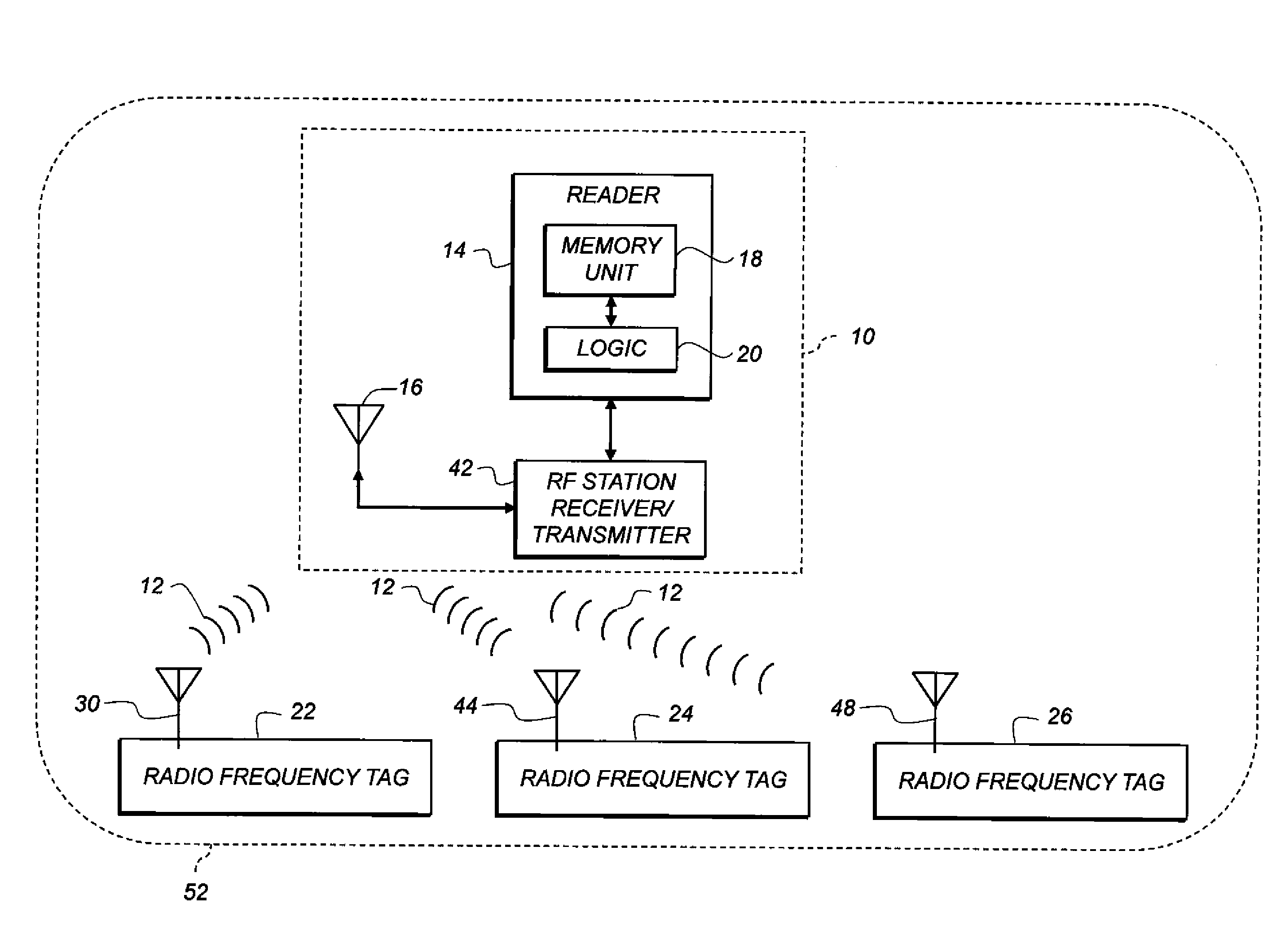
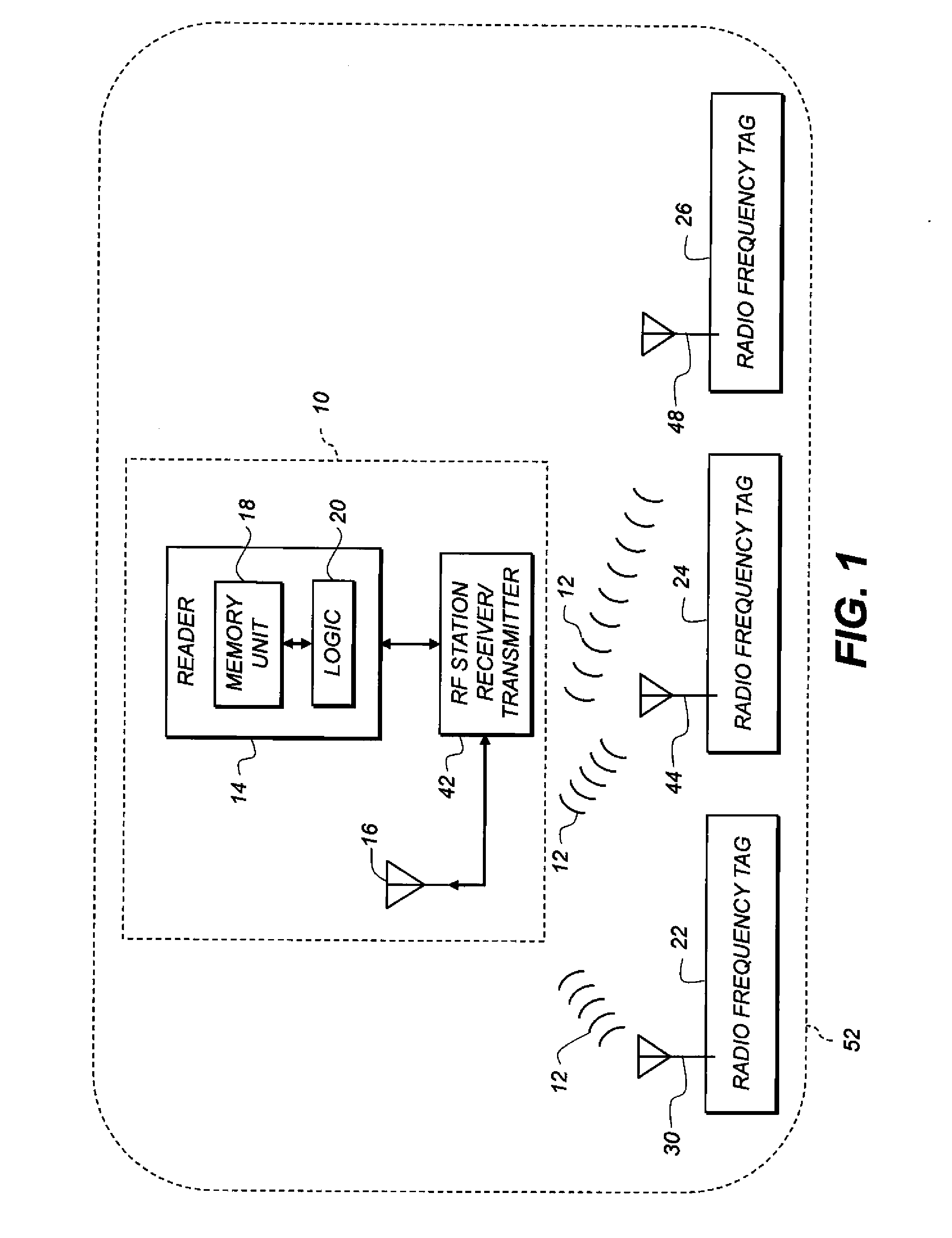
This patent describes a method for identifying different types of containers using RFID tags with directional antennas. The method involves placing the RFID tags on the container at different locations, each with a unique directional antenna. The RFID reader is then activated and the reader's antenna is placed in a specific location. The method allows for the automatic determination of the type of container based on which RFID tags are read. The invention also describes a method for reading multiple RFID tags using a single RFID reader and multiple antennas placed at different locations to detect attempts by skimmers to mimic valid tag signals. The technical effects of this invention are improved accuracy and security in identifying different types of containers and detecting skimming attempts.

Problems solved by technology

However, RFID tags in general, and specifically passive tags, often do not have enough processing power or memory to perform cryptographic authentication or authorization functions, such as secure hashing with time-varying salt.
As a result, RFID systems can be vulnerable to attacks in which a rogue (non-authorized) reader placed near a tag reads and stores that tag's data.
This can result in incorrect products being used in industrial or commercial processes, or mishandled inventory in a retail environment, possibly resulting in lost productivity or wasted product.
However, the blocker will disrupt all accesses, not just unauthorized access.
However, none of these schemes reduces the probability of passive monitoring by a skimmer during an authorized read of the tag.

Method used


Image

  • Container-type identification using directional-antenna RFID
  • Container-type identification using directional-antenna RFID
  • Container-type identification using directional-antenna RFID

Examples


Embodiment Construction

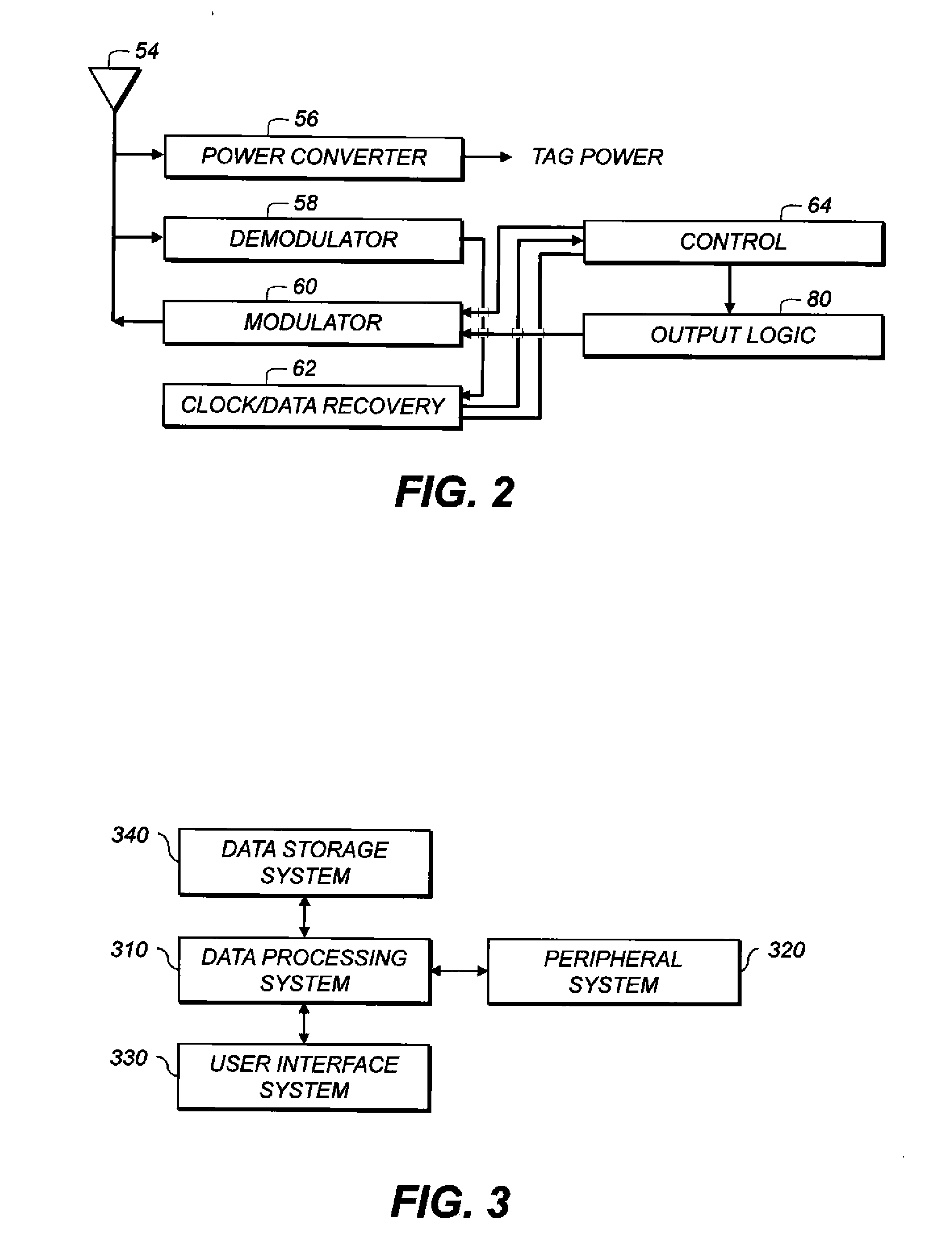
[0028]In the following description, some embodiments will be described in terms that would ordinarily be implemented as software programs. Those skilled in the art will readily recognize that the equivalent of such software can also be constructed in hardware. Because image manipulation algorithms and systems are well known, the present description will be directed in particular to algorithms and systems forming part of, or cooperating more directly with, methods described herein. Other aspects of such algorithms and systems, and hardware or software for producing and otherwise processing the image signals involved therewith, not specifically shown or described herein, are selected from such systems, algorithms, components, and elements known in the art. Given the system as described herein, software not specifically shown, suggested, or described herein that is useful for implementation of various embodiments is conventional and within the ordinary skill in such arts.

[0029]A comput...


PUM


Abstract

RFID tags are read using an RFID reader. A non-RFID-active object has two RFID tags affixed thereto at respective, different tag locations. Each tag has a respective directional antenna steered in a respective, different direction. Respective directional propagation patterns are thus defined and a reader location is defined in the intersection of the propagation patterns. An RFID reader with a reader antenna located at the reader location is provided. The RFID reader is activated to read both tags.

Description

CROSS-REFERENCE TO RELATED APPLICATIONS[0001]This application has related subject matter to U.S. patent application Ser. No. ______ (attorney docket No. K000945) filed herewith, titled “CONTAINER-CLASSIFICATION IDENTIFICATION USING DIRECTIONAL-ANTENNA RFID,”and U.S. patent application Ser. No. ______ (attorney docket No. K000946), filed herewith, titled “RFID MARKING OF UNITS IN A SPACE” the disclosures of which are hereby incorporated herein by reference.FIELD OF THE INVENTION[0002]This invention pertains to the field of radio-frequency communication between radio-frequency identification (RFID) tags and RFID readers, and more particularly to making it more difficult to perform unauthorized reads of tag data.BACKGROUND OF THE INVENTION[0003]Various electronic equipment or devices can communicate using wireless links. A popular technology for communication with low-power portable devices is radio frequency identification (RFID). Standardized RFID technology provides communication be...

Claims


Application Information

Patent Timeline
Patent Type & Authority Applications(United States)
IPC IPC(8): G06K7/01
CPCG06K7/10178
Inventor HINMAN, MARK P.RIMAI, DONALD SAULZOGG, EDWARD
Owner EASTMAN KODAK CO
Learn More