Electrical box with multi-directional partition plate

a technology of electric boxes and partition plates, which is applied in the direction of electric discharge tubes, electrical apparatus casings/cabinets/drawers, gas-filled discharge tubes, etc., to achieve the effect of economic production

Active Publication Date: 2013-12-05
HUBBELL INC
View PDF3 Cites 29 Cited by
  • Summary
  • Abstract
  • Description
  • Claims
  • Application Information

AI Technical Summary

Benefits of technology

[0019]A further feature of the invention is to provide an electrical box and electrical box assembly that can be used or without the partition plate. The electrical box and partition plate are constructed to avoid interference by the mounting assemb

Problems solved by technology

The divider intersects the entire interior volume of the box, including the knockout located in the back wall of the box, s

Method used


Image

  • Electrical box with multi-directional partition plate
  • Electrical box with multi-directional partition plate
  • Electrical box with multi-directional partition plate

Examples


Embodiment Construction

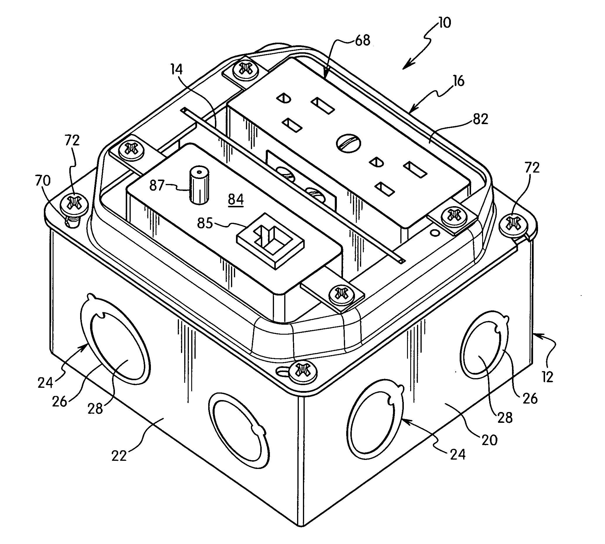
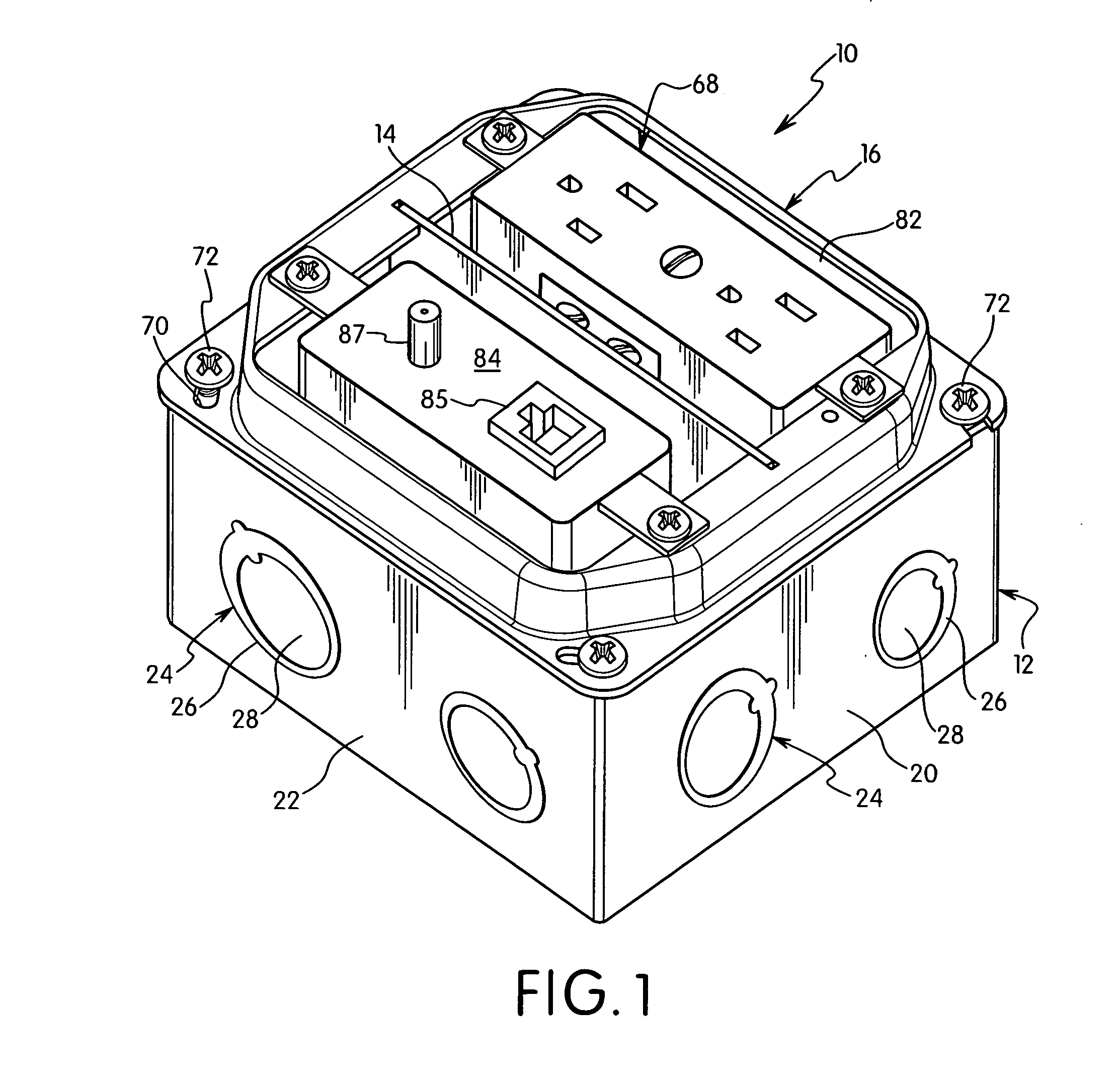
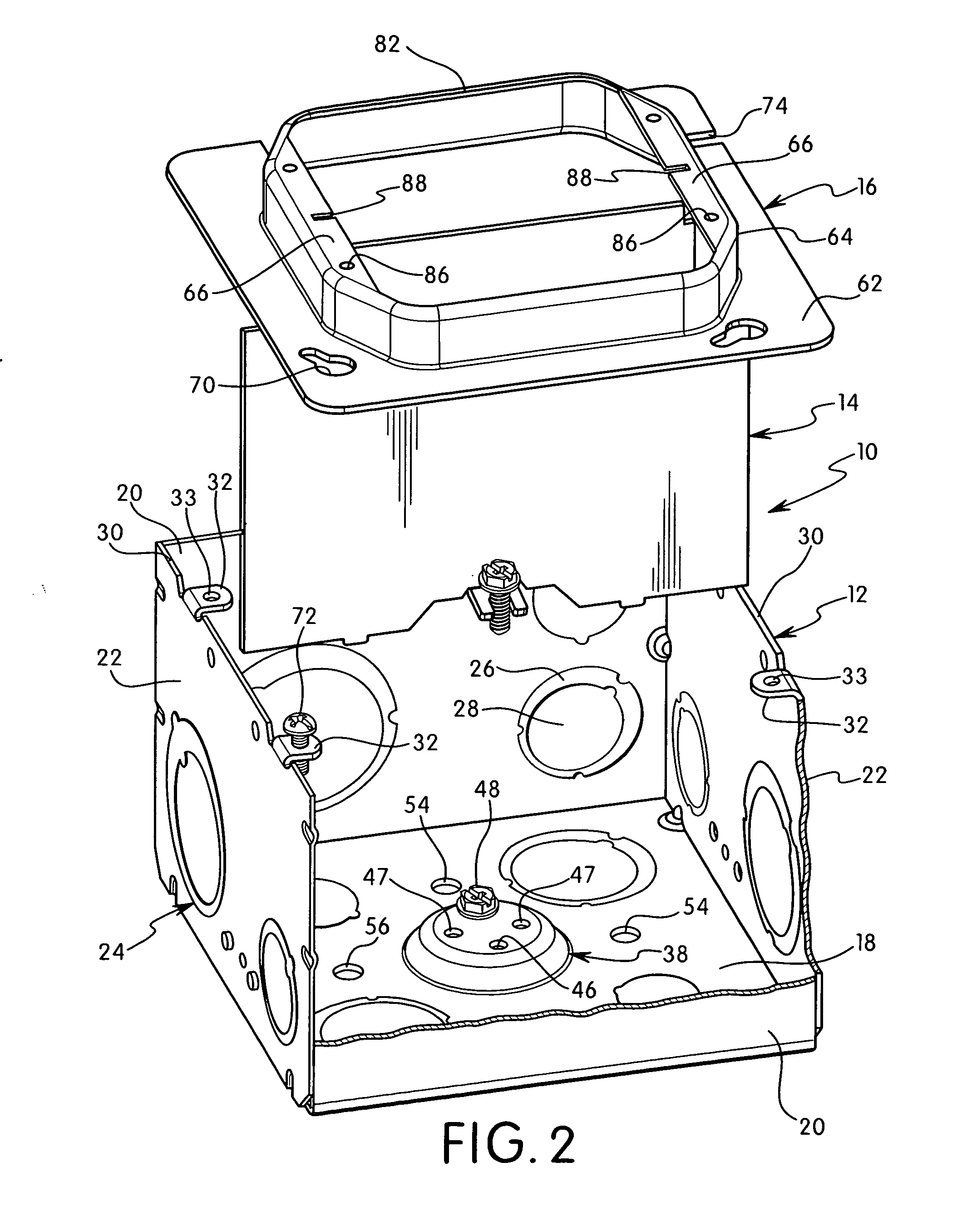
[0043]The present invention is directed to an electrical box and to an electrical box assembly having a removable partition plate. The invention is particularly directed to an electrical box assembly having a partition plate that can be mounted in different orientations with respect to the electrical box to form two separate compartments in the electrical box.

[0044]Referring to the drawings, the electrical box assembly 10 includes an electrical box 12, a partition plate 14, and a cover member 16. The electrical box 12 in a preferred embodiment as shown has a substantially square configuration with a rear wall 18 and side walls 20. Each of the side walls 20 has substantially the same width and height and are joined to the rear wall 18. The electrical box 12 preferably has a length substantially equal to its width. In one embodiment of the invention, the side walls 20 are integrally formed with the rear wall 18 and extend upwardly perpendicular to the rear wall. The side walls can be ...


PUM


Abstract

An electrical box assembly includes an electrical box, a movable partition plate, and a cover having an opening for receiving and supporting an electrical wiring device such as a switch or duplex receptacle. The electrical box has a rear wall with a centrally located emboss having a plurality of screw holes for receiving a ground screw and ground wire. The partition plate has a recess for mating with the emboss and a top end for coupling with the cover member. The partition plate and cover member are adapted for coupling to the electrical box in different orientations so that the partition plate divides the electrical box into substantially equal size compartments for receiving high voltage and low voltage requirements.

Description

FIELD OF THE INVENTION[0001]The present invention is directed to an electrical box and electrical box assembly. The invention is particularly directed to an electrical box assembly having a multi-directional partition plate for forming a high voltage compartment and a low voltage compartment.BACKGROUND OF THE INVENTION[0002]Electrical boxes are known for receiving electrical wiring for various wiring devices. The electrical boxes can stand alone or can be recessed in a wall, ceiling, floor, or other surface.[0003]Electrical boxes are also constructed for receiving high voltage wiring devices and low voltage wiring devices such as data and telephone receptacles. Boxes that receive both high voltage and low voltage require a divider to separate the high voltage and low voltage compartments.[0004]An example of an electrical box is disclosed in U.S. Pat. No. 6,218,613 to Justiniano et al. The electrical box includes a flexible, isolation barrier installed into a standard double-gang dev...

Claims


Application Information

Patent Timeline
IPC IPC(8): H02G3/14
CPCH02G3/14H02G3/086H02G3/08H02G3/081H02G3/121H05K5/00
Inventor KORCZ, KRZYSZTOF W.JOHNSON, STEVE J.AYRTON, MAHRAN H.
Owner HUBBELL INC
Why Eureka
Try Eureka