Compact Multiport Waveguide Switches

Active Publication Date: 2013-12-05
RUIZ CRUZ JORGE A +2
View PDF5 Cites 12 Cited by
  • Summary
  • Abstract
  • Description
  • Claims
  • Application Information

AI Technical Summary

Benefits of technology

[0006]The present invention provides a novel mechanism to implement waveguide switches. Instead of using rotating junctions, the switch is based on alternating short and open circuits in the propagation direction of the ridge waveguides. The shorts can be provided with a variety of very simple elements. Four-port C and R-type and, most importantly, T-type switches are provided using the same short circuit load concept. All the types are addressed with a very compact layout. These switches have the advantage of ha

Problems solved by technology

However, when several ports are involved, signal routing in waveguide switches (such as changes in the propagation direction

Method used


Image

  • Compact Multiport Waveguide Switches
  • Compact Multiport Waveguide Switches
  • Compact Multiport Waveguide Switches

Examples


Example

DETAILED DESCRIPTION OF THE DRAWINGS

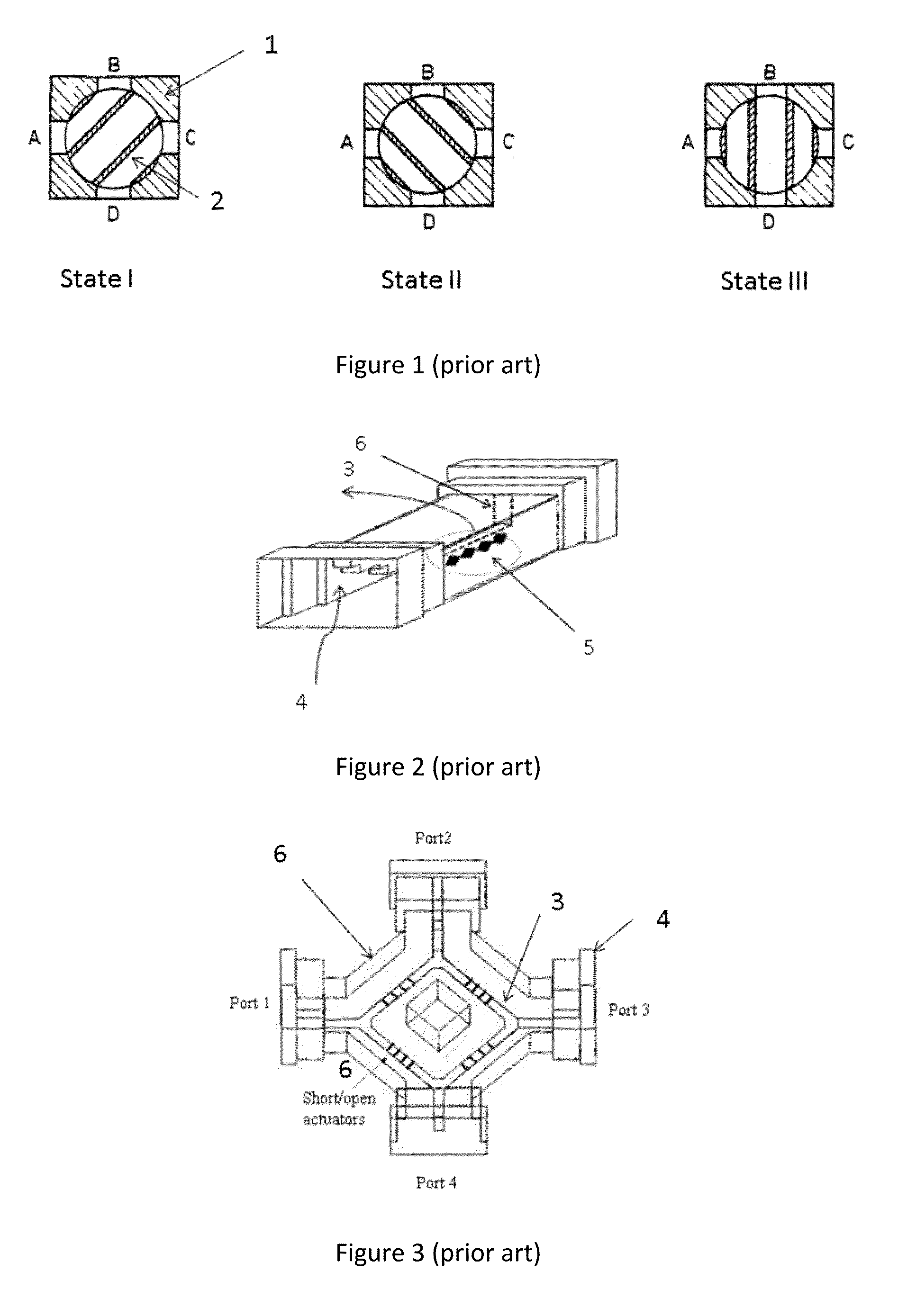
[0020]FIG. 1 shows a waveguide rotary switch (prior art). The body of switch 1 has four waveguide ports denoted by A, B, C and D. The switch uses a rotary mechanism 2 that rotates around its axis to create waveguide paths between the ports to establish the three states of the R-switch. For example, in state I, the rotary mechanism is turned such that to establish transmission between port A and port B and simultaneously establish transmission between port C and port D.

[0021]FIG. 2 shows a waveguide Single-Pole Single Through (SPST) switch (prior art) consisting of a ridge waveguide and two waveguide to ridge waveguide transformers. A set of short circuit loads 5 are used to connect the ridge 3 to the housing 6.

[0022]FIG. 3 shows a waveguide C-switch (prior art) comprising of four waveguide ports, sections of ridge waveguides 3 and four waveguide to ridge-waveguide transformers. Four sets of short circuits loads that can be actuated to provide a sh...


PUM


Abstract

A waveguide switch based on alternating short and open loads in a waveguide path. In one embodiment, the switch being made up of four waveguides connected by sections of ridge waveguides where simple short-circuit loads can be activated to control the signal paths. The switch being adapted for the C-, R- and T-type switches. Another embodiment of the same device being adapted for SPT type switched.

Description

FIELD OF THE INVENTION[0001]The present invention is related to microwave switches and more particularly to the realization of miniature multiport waveguide switches for high power applications.BACKGROUND OF THE INVENTION[0002]Waveguide switches are used in a broad range of applications with two main functions: They are used either to route signals for connecting the appropriate network elements or to provide redundancy schemes. Many spacecraft systems incorporate sophisticated switch matrices in order to increase the system reliability. They provide redundancy connections which are activated to bypass failing devices either automatically or by ground terminal commands.[0003]The switching networks are relatively easy to realize at low frequencies and at low signal power levels. The switches for low power applications are typically implemented using coaxial technology. Waveguide switches, on the other hand, are preferred in high frequency and for high power applications. However, whe...

Claims


Application Information

Patent Timeline
IPC IPC(8): H01P1/10H01P5/12
CPCH01P1/122H01P5/12
Inventor FAHMI, MOHAMED M.MANSOUR, RAAFAT R.
Owner RUIZ CRUZ JORGE A
Why Eureka
Try Eureka