Signal measuring method and device for touch screen
- Summary
- Abstract
- Description
- Claims
- Application Information
AI Technical Summary
Benefits of technology
Problems solved by technology
Method used
Image
Examples
first embodiment
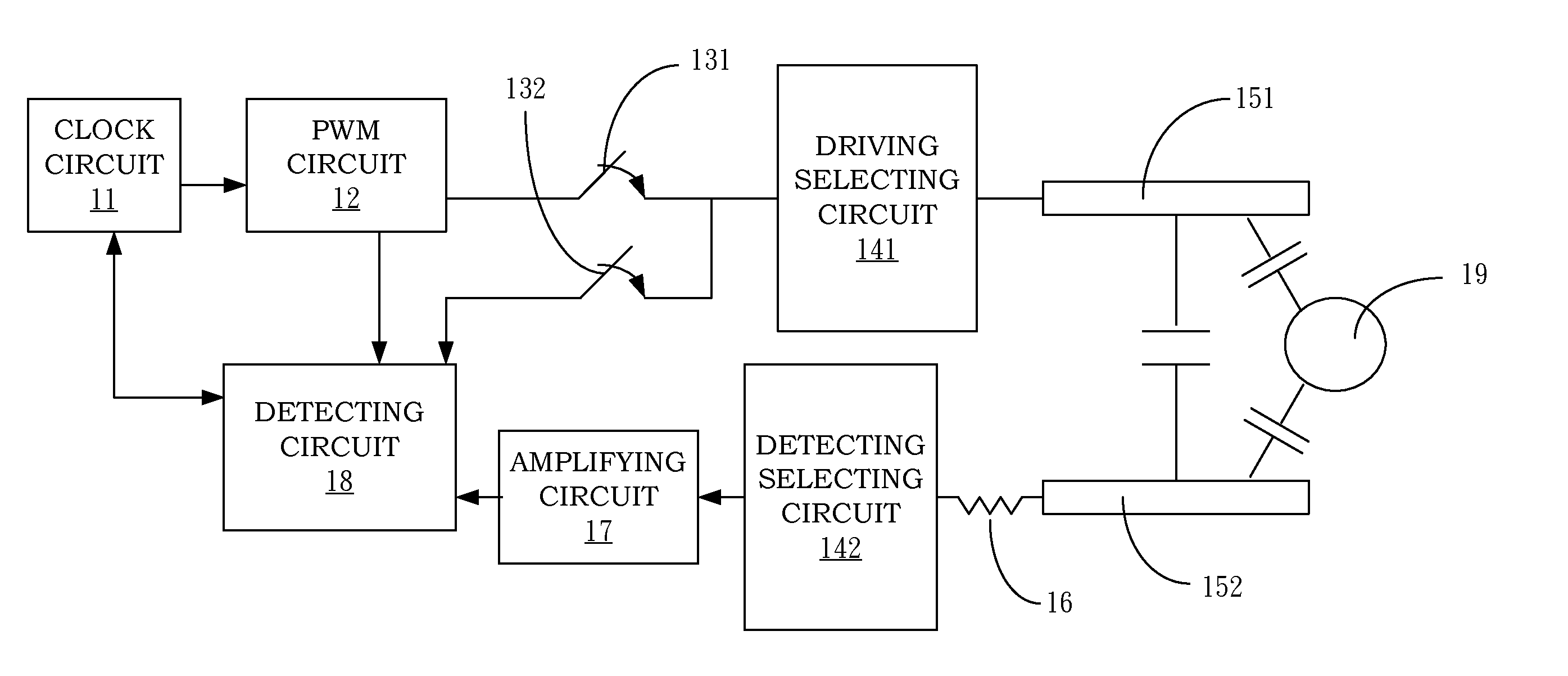
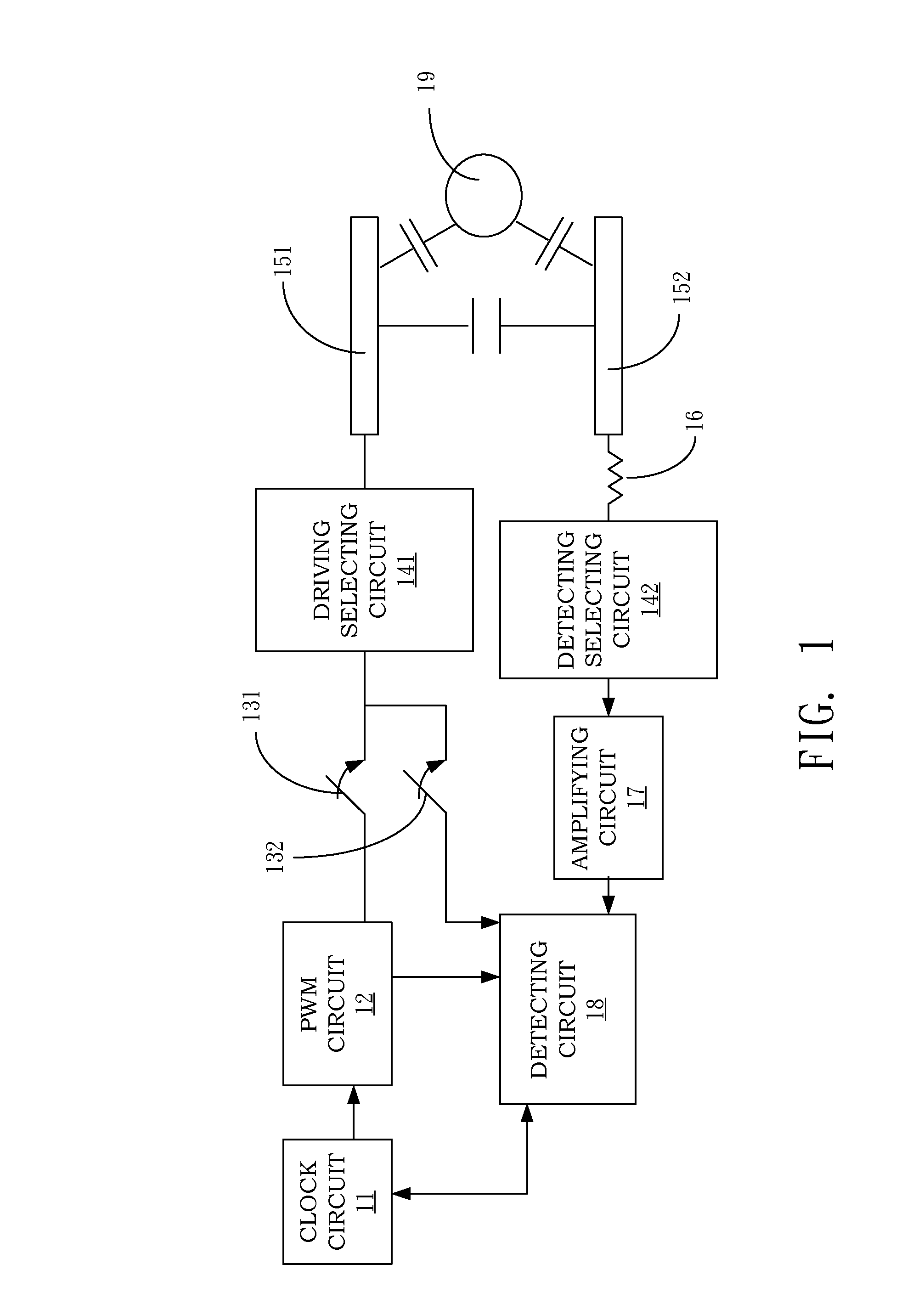
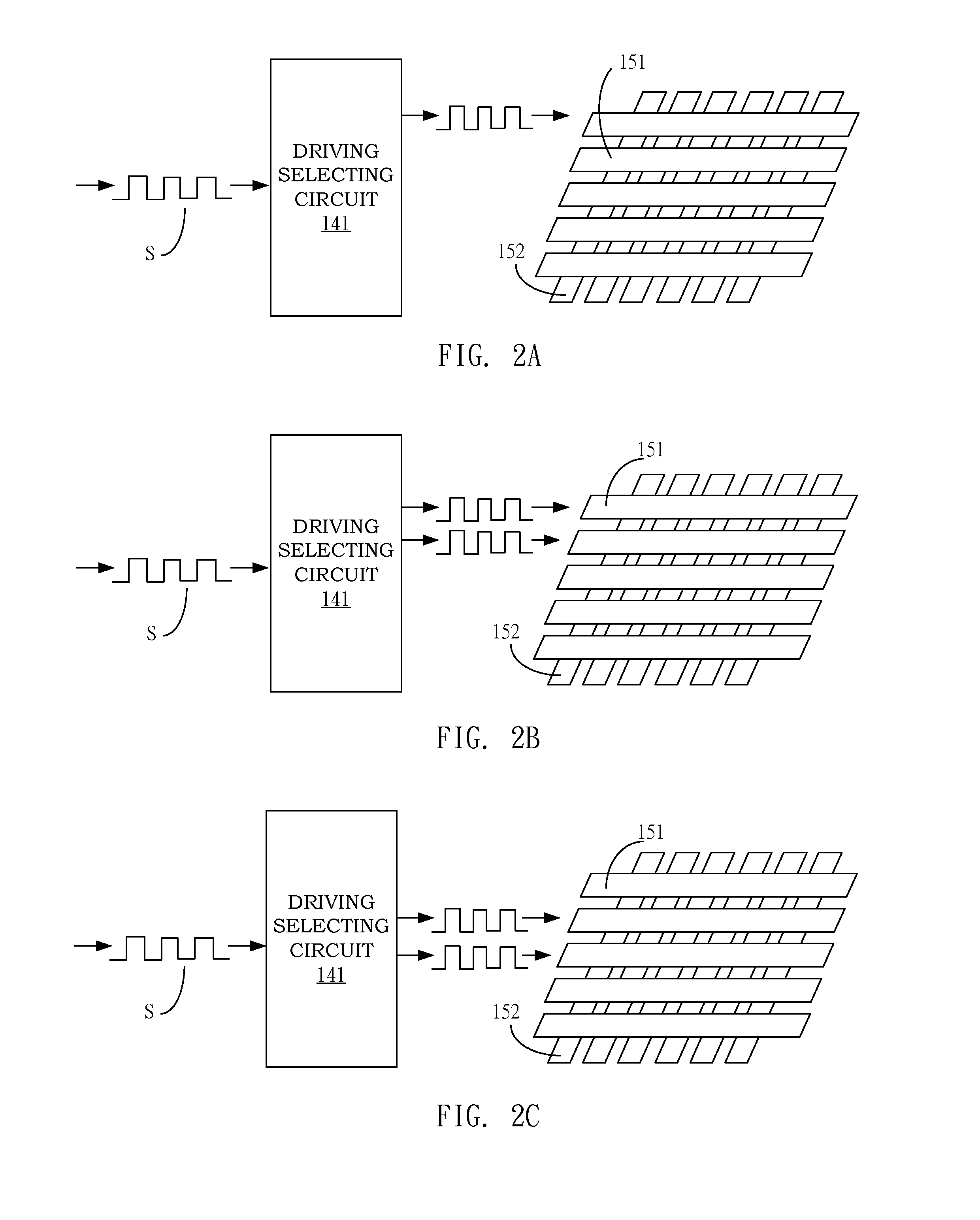
[0070]Accordingly, in best modes of the present invention, different phase differences are employed for different electrodes to delay the detected signals. For example, a plurality of phase differences are first determined, and when each set of driving electrodes are provided with the driving signal, one or more signals are measured based on each phase difference. Among the measured signals, the phase difference on which the largest signal is based will be closest to the phase difference between the signal before being provided to the driving electrode(s) and the signal received by the sensing electrode; this phase difference is hereinafter referred to as the closest phase difference. Said signal measuring can be performed by selecting and measuring just one of the sensing electrodes based on each phase difference, or selecting and measuring a plurality or all of the sensing electrodes based on each phase difference, and then the closest phase difference is determined based on the s...
second embodiment
[0085]In the present invention, signals are measured by a control circuit. The signal of each set of sensing electrodes is first passed through a variable resistor before being measured. The control circuit determines the impedance of the variable resistor based on each set of the driving electrodes. For example, a set of driving electrodes is selected as basis electrodes, while the rest of the electrodes are regarded as non-basis electrodes. A plurality of predetermined impedances are set in advance, and a signal of one sensing electrode or a sum of signals of some or all of the sensing electrodes is detected when the basis electrodes (which may be one or more) is / are provided with the driving signal, and used as a levelized signal. In addition, the levelized signal can fall within a predetermined working range; it does not need to be the optimum or the largest signal. In other words, any predetermined impedance that allows the levelized signal to fall within a predetermined workin...
third embodiment
[0088]In the present invention, signals are measured by a control circuit. The signal of each set of sensing electrodes is first passed through a measuring circuit (e.g. an integrator) before being measured. The control circuit determines the amplifying ratio of the measuring circuit based on each set of the driving electrodes. For example, a set of driving electrodes is selected as basis electrodes, while the rest of the electrodes are regarded as non-basis electrodes. A plurality of predetermined amplifying ratios are set, and a signal of one sensing electrode or a sum of signals of some or all of the sensing electrodes is detected when the basis electrodes (which may be one or more) is / are provided with the driving signal, and used as a levelized signal. In addition, the levelized signal can fall within a predetermined working range; it does not need to be the best or the largest signal. In other words, any predetermined amplifying ratio that allows the levelized signal to fall w...
PUM
 Abstract
Description
Claims
Application Information
 - R&D Engineer
- R&D Manager
- IP Professional
- Industry Leading Data Capabilities
- Powerful AI technology
- Patent DNA Extraction
Browse by: Latest US Patents, China's latest patents, Technical Efficacy Thesaurus, Application Domain, Technology Topic, Popular Technical Reports.
© 2024 PatSnap. All rights reserved.Legal|Privacy policy|Modern Slavery Act Transparency Statement|Sitemap|About US| Contact US: help@patsnap.com


