
Cursor driven interface for layer control

a layer control and interface technology, applied in the field of cursor driven interfaces for layer control, can solve the problems of difficult manipulation with a pointing device, affecting the quality of the layer control interface,

Active Publication Date: 2013-12-05
DOOR NUMBER 3
View PDF11 Cites 97 Cited by
  • Summary
  • Abstract
  • Description
  • Claims
  • Application Information

AI Technical Summary

Benefits of technology

The patent describes an approach for creating a centralized, shared, collaborative online drawing environment. The approach includes displaying a plurality of elements and allowing users to select and interact with the elements. The display order of the elements can be changed based on user input. This allows for easy collaboration and sharing of drawings. The patent also describes a method for adjusting the speed at which the interface element is being adjusted to match the user's speed. Overall, the patent provides a technical solution for creating a more efficient and effective online drawing platform.

Problems solved by technology

While text documents are particularly well suited to these shared collaborative models, documents such as drawings, graphs, pictures and other graphical elements have characteristics that do not lend themselves to online collaboration.
If the juncture of two lines is displayed differently on two devices, even being offset by a tiny amount, the entire drawing will be compromised.
Graphical documents often contain numerous layers of graphic objects, which may be difficult to manipulate with a pointing device, such as a mouse or fingertip in the case of a touchscreen device.
Another difficulty in providing a shared collaborative drawing model is the need for perfect synchronization wherein each individual user's version of the drawing to be shared must be identical to the other members of the group of users taking actions on the drawing such as viewing, commenting or modifying the drawing.
Using the native drawing routines of each device results in consistencies between renditions of each panel on the various platforms.
This is further complicated when a toolbar is hidden, then creating 3 separate gestures for switching tools, and then 3 again to switch back.
All of these steps further distance the usage of the digital tablet from the ease of its analog sister, the traditional whiteboard.
Having many objects stacked in this manner causes difficulty in altering or rearranging the z-order of an object in one of these applications.
As a result, a difficulty presented is that with the tools hidden, changes from one tool to another become difficult and involve many steps of showing and hiding toolbars, etc.

Method used


Image

  • Cursor driven interface for layer control
  • Cursor driven interface for layer control
  • Cursor driven interface for layer control

Examples


Embodiment Construction

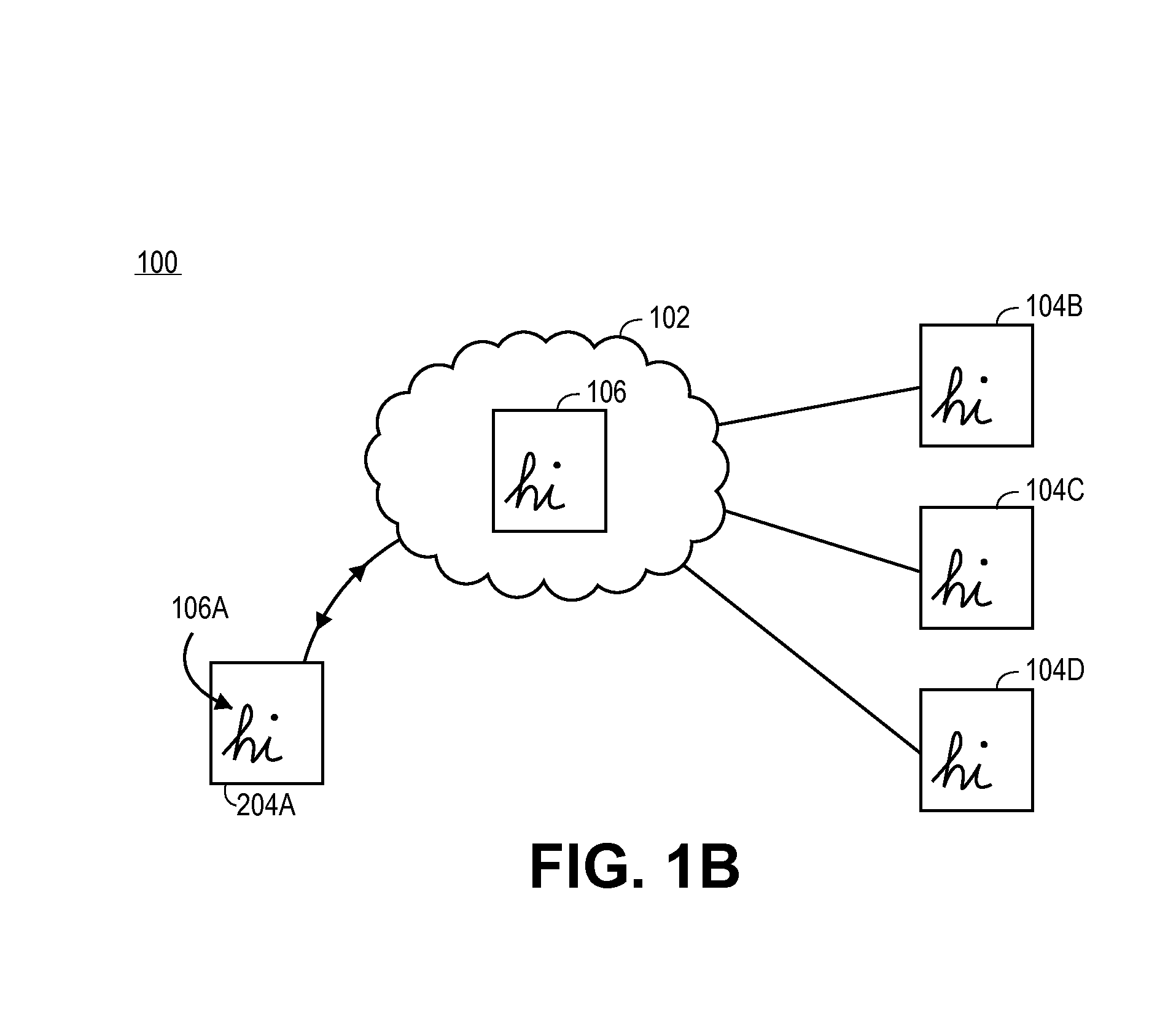
[0019]Approaches for devices, methods and software for providing a centralized, shared, collaborative, online drawing environment and the related infrastructure, data structures, drawing models, and user interface elements and approaches are described. In the following description, for the purposes of explanation, numerous specific details are set forth in order to provide a thorough understanding of the embodiments described herein. It will be apparent, however, that the embodiments described herein may be practiced without these specific details. In other instances, well-known structures and devices are shown in block diagram form in order to avoid unnecessarily obscuring the embodiments described herein.

Functional Overview

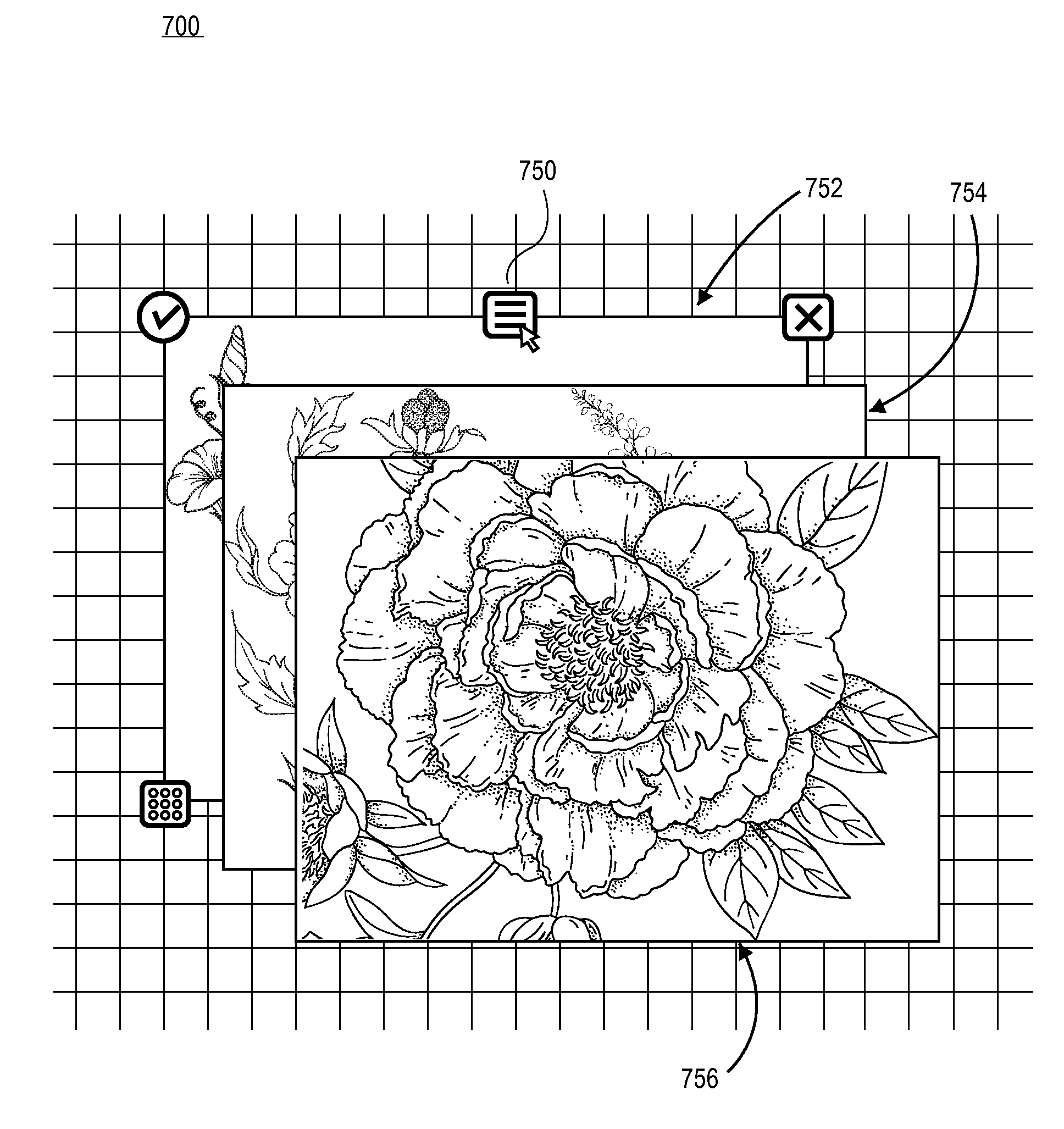
[0020]Embodiments of the approaches described herein may comprise displaying a plurality of elements wherein the elements are stacked in a display order, and causing a first element (or multiple elements) of the plurality of elements to be selected as the active...


PUM


Abstract

An approach for manipulating objects within a document whereby one or more objects are transposed between other objects in a display order. A first element of the plurality of elements is selected as the active element and a display interface is associated with the first element, and based on input received with respect to the interface element, the display order of the first element is changed in relation to the plurality of elements.

Description

CLAIM OF PRIORITY AND RELATED APPLICATION DATA[0001]This application claims priority to U.S. provisional patent application Ser. No. 61 / 649,759, filed May 21, 2012, the contents of which are hereby incorporated by reference for all purposes as if fully set forth herein.[0002]This application is related to U.S. patent application Ser. No. 13 / 898,318, filed on May 20, 2013, entitled “Common Drawing Model”, by Benjamin P. Bauermeister et al., the contents of which are hereby incorporated by reference for all purposes as if fully set forth herein.BACKGROUND[0003]The growth of the Internet and high-speed network connections has enabled the proliferation of collaborative document creation and modification. Multiple users are able to create, view, edit and comment on a single document, often in real-time. While text documents are particularly well suited to these shared collaborative models, documents such as drawings, graphs, pictures and other graphical elements have characteristics that...

Claims


Application Information

Patent Timeline
IPC IPC(8): G09G5/377
CPCG09G5/377G06F3/1462G09G2370/022G06F3/0488G06F3/04883G06F3/017G06F3/0482
Inventor BAUERMEISTER, BENJAMIN P.FLAGG, NEIL A.
Owner DOOR NUMBER 3
Learn More