
Display Device, Backlight Module and Mainframe structure Unit Thereof

a backlight module and display device technology, applied in the field of backlight modules and frame units, can solve the problems of poor stability of the overall configuration, inability to engage screws, and inability to separate the plastic frame and the backboard, so as to improve the stability and reliability of the plastic frame

Inactive Publication Date: 2013-12-05
TCL CHINA STAR OPTOELECTRONICS TECH CO LTD
View PDF1 Cites 9 Cited by
  • Summary
  • Abstract
  • Description
  • Claims
  • Application Information

AI Technical Summary

Benefits of technology

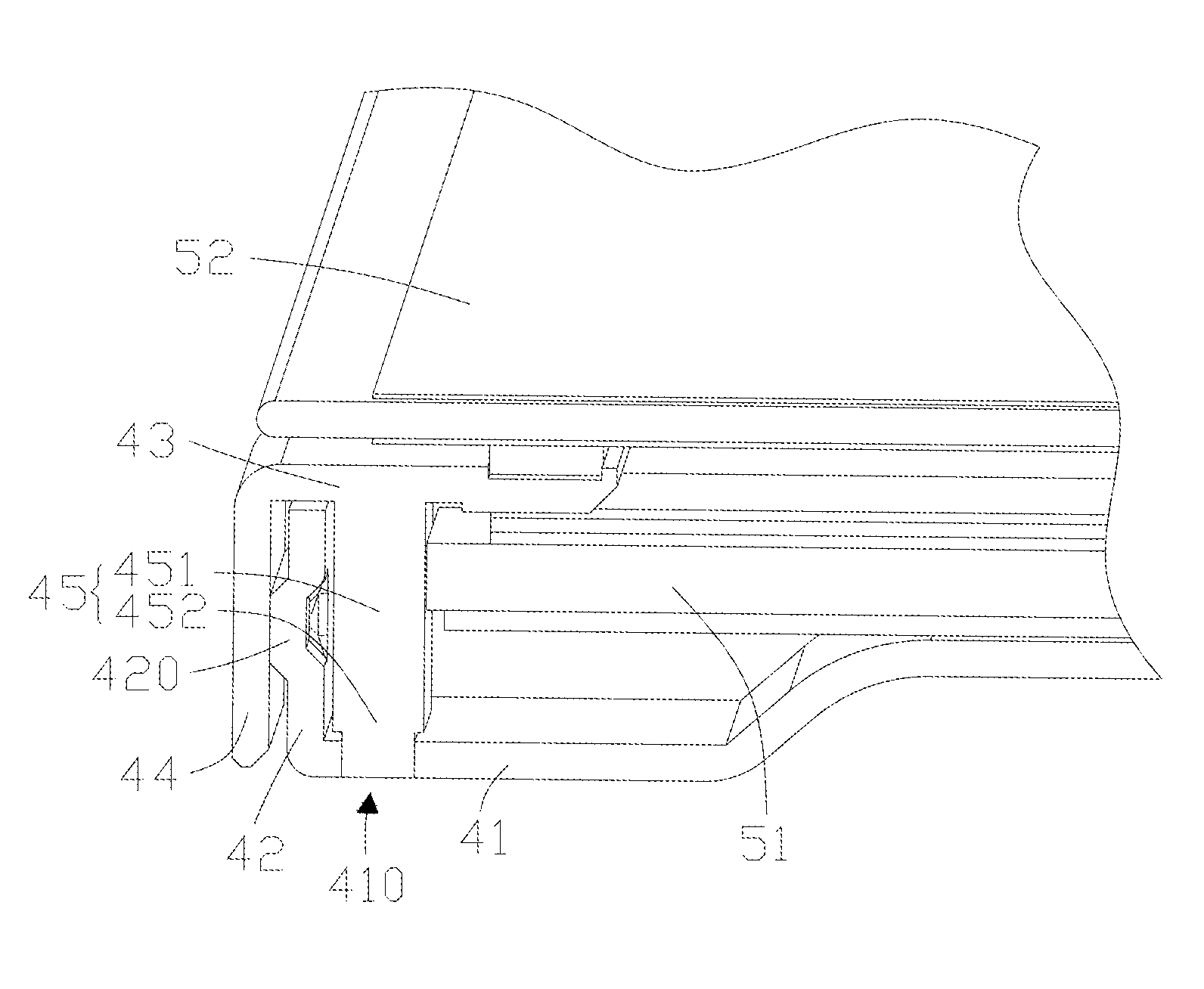
The purpose of this patent is to enhance the stability and reliability of a plastic frame used in a display device. This is achieved by interconnecting the plastic frame to a carrying portion with a supporting main portion, and positioning the plastic frame in place using a positioning block and bottom. This prevents the plastic frame from being crushed due to its compression and ensures proper positioning of the optical films. Additionally, the mainframe structure is designed to be firm and reliable, with a longer service life for the final product.

Problems solved by technology

However, the mere engagement with screws is not reliable and with poor shock prevention such that separation between the plastic frame and the backboard could be happened once external forces are applied.
As a result, the stability of the Overall configuration is poor.
However, sharp edges of the protections of the backboard can readily scratch the liquid crystal display panel.
Accordingly, the fixture to the liquid crystal display is really poor.

Method used


Image

  • Display Device, Backlight Module and Mainframe structure Unit Thereof
  • Display Device, Backlight Module and Mainframe structure Unit Thereof
  • Display Device, Backlight Module and Mainframe structure Unit Thereof

Examples


first embodiment

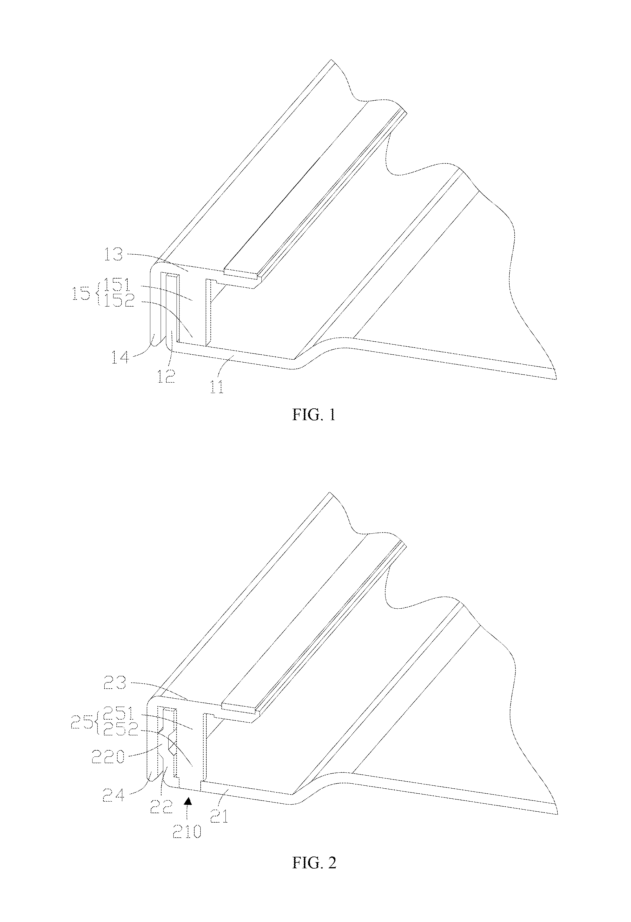
[0035]In the current embodiment, the plastic frame is interconnected to the carrying portion 13 by means of the supporting main portion 151 of the supporting portion 15, the positioning portion 152 is engaged with the bottom 11, for example, by abutting against, screwing, or welding. As a result, the carrying portion. 13 of the plastic frame can securely support the liquid crystal display panel, while will not be crushed because of its compression. As a result, the optical .films are also properly positioned. In addition, since the positioning block 152 and the bottom 11 can effectively prevent the transversal movement of the plastic frame when the plastic frame is exposed with external pressure, accordingly, the stability and firmness of the Plastic frame are enhanced. As such, the mainframe structure made in according to the present invention is firm and reliable without readily being damaged, the service life of the final product is also prolonged.

second embodiment

[0036]Referring to FIG. 2, which is a partial and structural view of a mainframe structure made in accordance with the present invention.

[0037]The mainframe structure can be preferably incorporated into a backlight module, and which is configured with the backboard and the plastic frame, but not limited thereto. As described above, the backboard includes a bottom 21 and a first sidewall 22, and the plastic frame includes a carrying portion 23, a second sidewall 24 and a supporting portion 25 which is configured with a supporting main portion 251 and a positioning block 252. In addition, both the backboard and the plastic frame are not limited to be configured such elements. Furthermore, the internal relationship of those elements and parts are identical to what disclosed in the first embodiment, as such, no further description is given below.

[0038]The difference between the first and second embodiments is: the bottom 21 is provided with a positioning portion 210, and the supporting ...

third embodiment

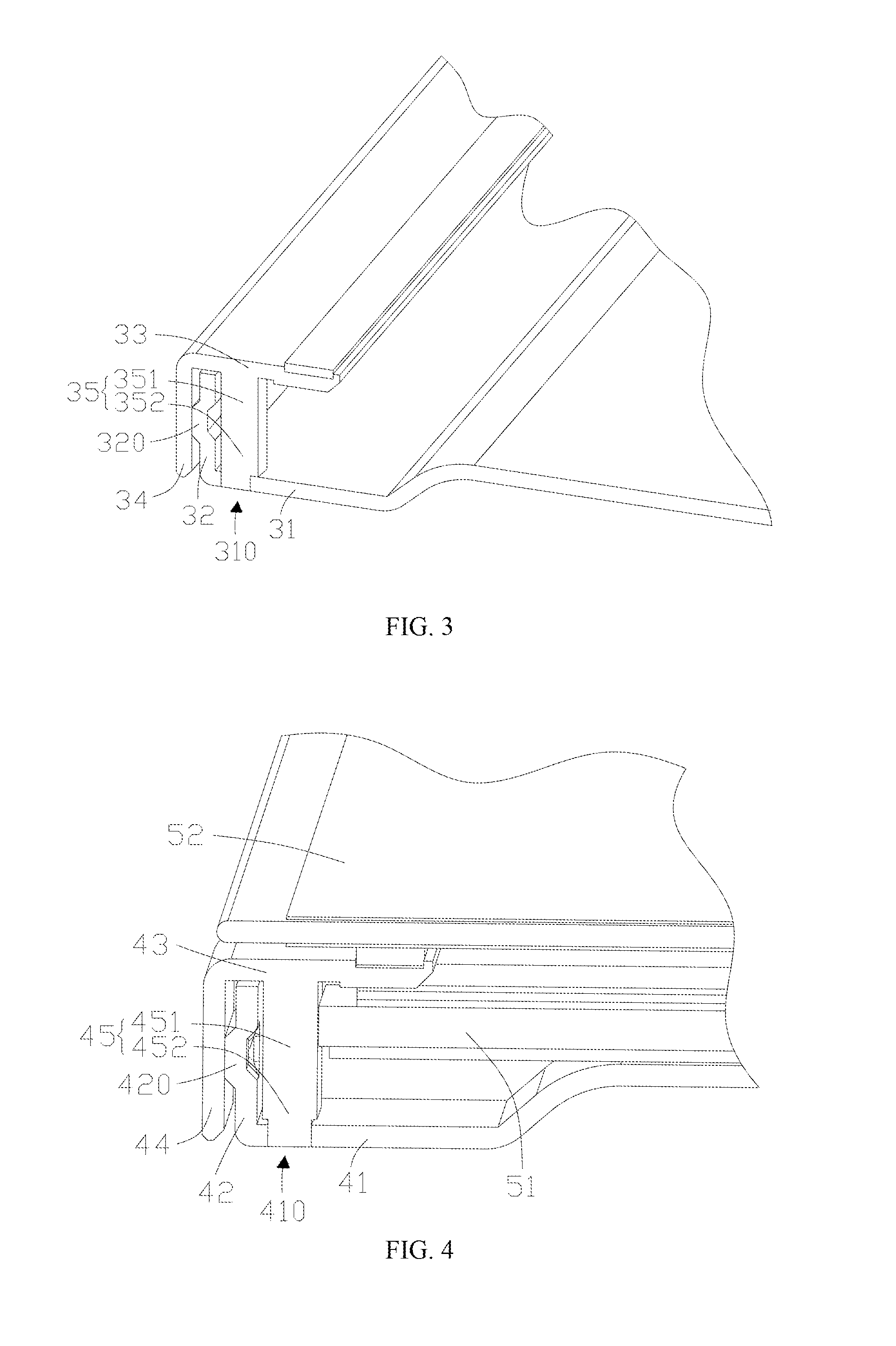
[0041]Referring to FIG. 3 which is a partial and structural view of a mainframe structure made in accordance with the present invention.

[0042]In the current embodiment, the mainframe structure is preferably included in the backlight module. The mainframe structure at least includes a backboard and a plastic frame. As disclosed above, the backboard includes but not limited to the bottom 31, the first sidewall 32. The plastic frame includes a carrying portion 33, a second sidewall 34, and a supporting portion 35. The supporting portion 35 includes a supporting main portion 351 and a positioning block 352. The bottom 31 is provided with a positioning portion 310. The first sidewall 32 is provided with a fastener 320. The detailed configuration of the fastener 320 can be referred to the embodiments disclosed above. As it is within the knowledge of the ordinary skilled in the art. No details are given here below.

[0043]The difference between this and the second embodiment is that the posi...


PUM

PropertyMeasurementUnit
distanceaaaaaaaaaa
structureaaaaaaaaaa
external forcesaaaaaaaaaa

Abstract

The present invention discloses a display device which is configured with a liquid crystal display panel and a backlight module. The backlight module includes at least an optical film and a mainframe structure which includes a plastic frame and a backboard integrally with the plastic frame. The backboard includes an integral bottom to support the optical films of the backlight module, and a first sidewall. Wherein the plastic frame is integrally formed with a carrying portion. a second sidewall, and a supporting portion, wherein the carrying portion is used to position optical films, and also support the liquid crystal display panel, wherein to receiving slot is defined, between the second sidewall and the supporting main portion such that the first sidewall is received therein, wherein the supporting portion includes an integrally formed main portion interconnected to the carrying portion and a positioning block which prevent the plastic frame from transversal movement with respect to the backboard together with the bottom of the backboard. The present invention readily increases the stability and firmness of the plastic frame.

Description

FIELD OF THE INVENTION[0001]The present invention relates to a technologic field of liquid crystal display, and more particularly to a backlight module and a frame unit incorporated with the backlight module. The present invention further includes a liquid crystal display device incorporated with such a backlight module.DESCRIPTION OF PRIOR ART[0002]Currently, a backlight module used in a liquid crystal display device generally includes a mainframe, structure configured with a plastic. frame and a backboard. The plastic frame and the backboard are interengaged by means of sidewalls of the plastic frame.[0003]Substantially, the plastic frame has the sidewall corresponding to the sidewalls of the backboard. In assembling, screws Or other suitable fastening devices or arrangements can be applied. However, the mere engagement with screws is not reliable and with poor shock prevention such that separation between the plastic frame and the backboard could be happened once external forces ...

Claims


Application Information

Patent Timeline
Patent Type & Authority Applications(United States)
IPC IPC(8): G02F1/13357G09F13/04F21V17/08
CPCG02F1/133608G09F13/04G02F1/133317G02F1/133322
Inventor CHENG, JIAHE
Owner TCL CHINA STAR OPTOELECTRONICS TECH CO LTD
Learn More