Shank Structure of End Mill and Tool Holder

a technology of end mills and tool holders, which is applied in the direction of attachable milling devices, shaping cutters, manufacturing tools, etc., can solve problems such as axis dislocation, and achieve the effects of reliably pressing the flat surface, reducing the chance of axis dislocation, and reducing the risk of axis dislocation

Active Publication Date: 2013-12-05
NIKKEN KOSAKUSHO WORKS LTD
View PDF6 Cites 9 Cited by
  • Summary
  • Abstract
  • Description
  • Claims
  • Application Information

AI Technical Summary

Benefits of technology

[0020]In an embodiment, the side lock bolt includes a bolt body that is screwed in the through hole, and a pressing member having a pressing surface that abuts on the shank portion of the end mill, and being attached to a tip end of the bolt body so that orientation of the pressing surface can be changed as desired. In this embodiment, even if the flat surface of the shank portion does not extend in a direction that crosses a direction in which the side lock bolt advances, the pressing surface at the tip end of the side lock bolt changes its orientation according to the flat surface of the shank portion and surface contacts the flat surface when the side lock bolt is rotated in the fastening direction. Accordingly, the side lock bolt firmly presses the flat surface of the shank portion, and the shank portion can be more reliably chucked.
[0021]In a preferred embodiment, the flat tip end face of the side lock bolt may be surface-treated so as to have a higher friction coefficient. In this embodiment, the surface-treated tip end face of the side lock bolt is less likely to slide on the flat surface of the shank portion when the surface-treated tip end abuts on the flat surface of the shank portion. Thus, the side lock bolt can reliably press the flat surface. This makes it more difficult for the shank portion to come off from the tool holder. Examples of this surface treatment include a shot peening process and a plating process. Alternatively, other physical or chemical treatment may be performed. The side lock bolt that is surface-treated so as to have a higher friction coefficient is at least one of the first and second side lock bolts. The flat surface of the shank portion which abuts on the tip end face of this side lock bolt is at least one of the first and second flat surfaces.
[0022]Thus, in the shank structure of the present invention, the shank portion of the end mill is not subjected to the specific radial force, and improved chucking is provided.

Problems solved by technology

Moreover, displacement of the axis may occur.

Method used


Image

  • Shank Structure of End Mill and Tool Holder
  • Shank Structure of End Mill and Tool Holder
  • Shank Structure of End Mill and Tool Holder

Examples


Embodiment Construction

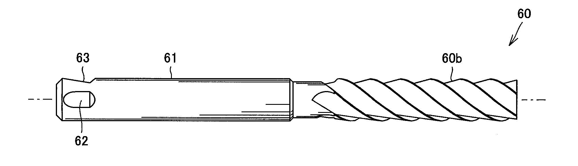
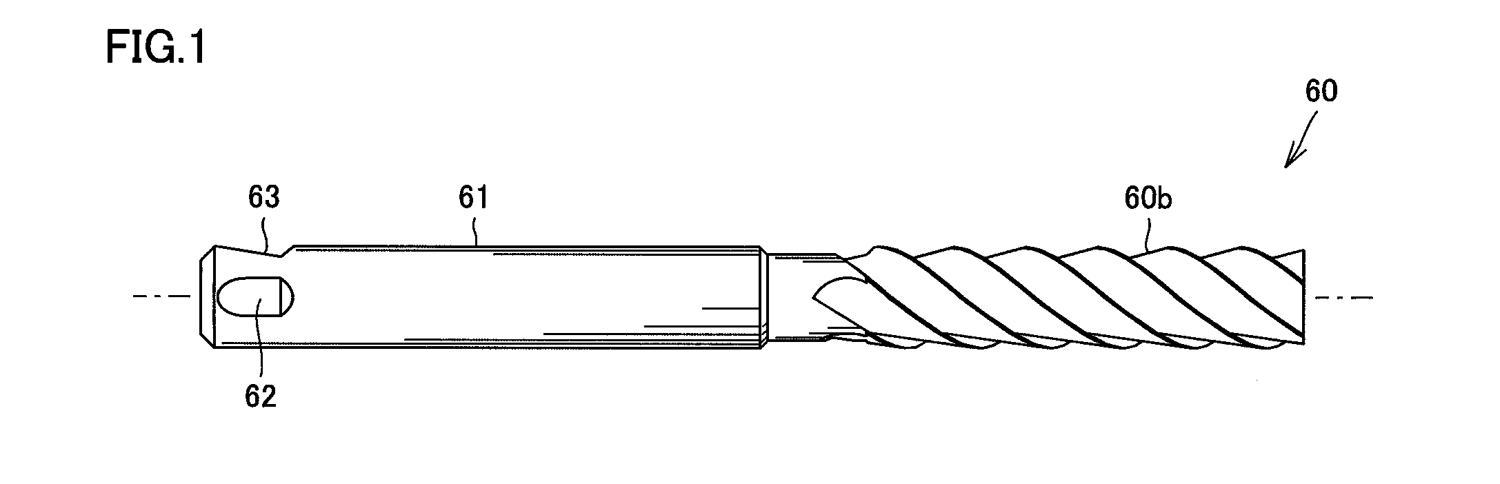
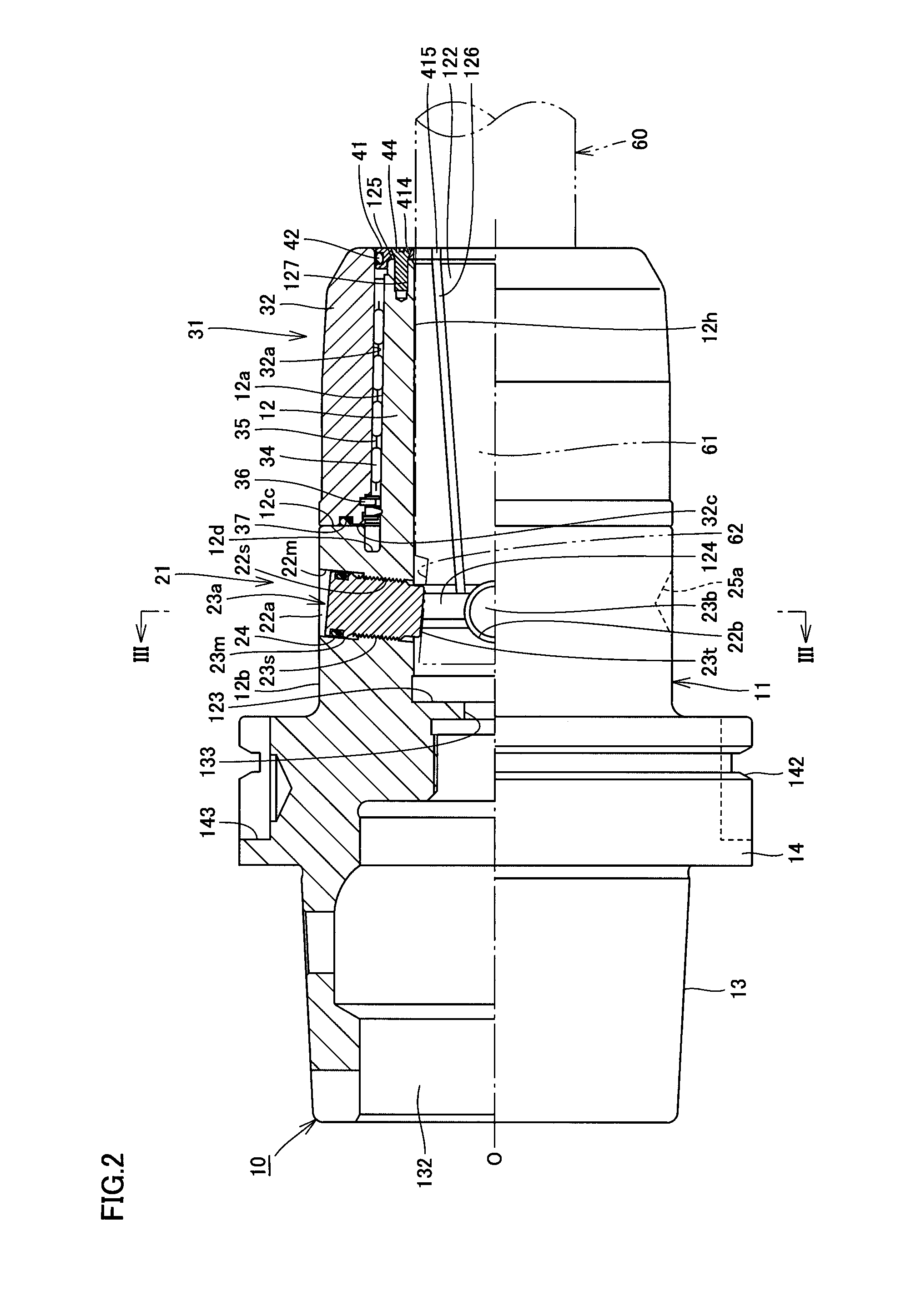
[0040]Embodiments of the present invention will be described in detail below with reference to the accompanying drawings. FIG. 1 is a side view showing an end mill according to an embodiment of the present invention. FIG. 2 is an overall view showing a tool holder according to an embodiment of the present invention. FIG. 3 is a transverse sectional view showing the tool holder and the end mill of the embodiment taken along line III-III in FIG. 2, as viewed from the direction shown by an arrow. FIG. 4 is a front view showing an axial tip end of the tool holder of the embodiment. FIG. 5 is a front view showing the axial tip end of the tool holder of the embodiment having a lid member removed therefrom. FIG. 6 is an overall view showing a groove formed in an inner peripheral surface of a tool attaching / detaching portion of the tool holder of the embodiment. FIG. 7 is an overall view showing the tool holder of the embodiment before chucking, which is not holding a shank portion of the e...


PUM

PropertyMeasurementUnit
angleaaaaaaaaaa
angleaaaaaaaaaa
angleaaaaaaaaaa

Abstract

In a shank portion of an end mill which is chucked by a tool holder, flat surfaces are formed at a plurality of circumferential positions in the outer periphery of the shank portion so that the flat surfaces abut on side lock bolts attached to a body of the tool holder.

Description

BACKGROUND OF THE INVENTION[0001]1. Field of the Invention[0002]The present invention relates to shank portions of end mills among cutters such as end mills and reamers, and tool holders that chuck the shank portion of the end mill.[0003]2. Background Art[0004]Conventionally, shank portions of cutters such as end mills and reamers, and tool holders that chuck the shank portion of the cutter are proposed in, e.g., Japanese Unexamined Patent Publication Nos. 2002-346864 and 2001-87969 and Japanese Utility Model Publication No. H06-80509. Such conventional tool holders include two side lock bolts. The shank portion of the cutter basically has a circular cross section, and two flat surfaces are formed in the outer periphery of the shank portion. By fastening the two side lock bolts, the tip ends of the side lock bolts abut on the flat surfaces, respectively, whereby the shank portion of the cutter is chucked.SUMMARY OF INVENTION[0005]The inventors found that there is still room for impr...

Claims


Application Information

Patent Timeline
Patent Type & Authority Applications(United States)
IPC IPC(8): B23C5/26B23C5/28B23C5/10
CPCB23B31/1075B23B31/005B23B31/117B23B2231/0256B23B2250/12Y10T279/17821Y10T407/14Y10T407/1948Y10T409/30952
Inventor NAKAI, EISAKUMAEMURA, SUGURUMIKADO, SUSUMUECKERSALL, STEVE
Owner NIKKEN KOSAKUSHO WORKS LTD
Why Eureka
Try Eureka