Image forming apparatus

a technology inner finisher, which is applied in the direction of electrographic process apparatus, instruments, optics, etc., can solve the problems of image forming apparatuses provided with a conventional inner finisher, enlargement of the apparatus as a whole, and contrary to the demands for a more compact apparatus, so as to reduce the number of components, reduce the cost, and the effect of compact apparatus siz

Inactive Publication Date: 2006-07-20
SHARP KK
View PDF5 Cites 7 Cited by
  • Summary
  • Abstract
  • Description
  • Claims
  • Application Information

AI Technical Summary

Benefits of technology

[0036] In this manner, by also using the rollers of the discharge roller portion as shifter rollers, it is possible to achieve a reduction in the number of components, a reduction in cost, a more compact size for the apparatus, and the like. Also, disposing the rollers used for paper discharge such that they can be put in contact or separated gives rise to the following sort of merits. Conventionally, a configuration is adopted in which, when discharge rollers have been used as shifter rollers, shifter processing is not performed when staple processing has been performed. That is, because the discharge rollers cannot be put in contact or separated, the shifter function of the discharge rollers is only applicable to one page of paper for which staple processing has not been performed, and is not applicable to a paper batch for which staple processing has been performed. On the other hand, as described above, by disposing the rollers used for paper discharge such that they can be put in contact or separated, after staple processing, by putting the drive roller and the idler roller with which it forms a pair in a contact state, it is possible to reliably chuck a paper batch after staple processing, and shifter processing can be performed in this state. Thus, it is possible to likewise perform shifter processing for either one page of paper for which staple processing has not been performed, or a paper batch for which staple processing has been performed.

Problems solved by technology

However, for example, as disclosed in JP 2004-145200A, in an image forming apparatus using a built-up system, designing a paper post-processing apparatus on the side face of the image forming apparatus main body leads to enlargement of the apparatus as a whole, and is contrary to demands for a more compact apparatus.
However, image forming apparatuses provided with a conventional inner finisher have the following sorts of problems.
In such a case, there is the problem that with the pair of discharge rollers that discharge the paper to the discharging means from the staple processing stage in a contact state, staple processing cannot be performed for paper that is longer than the length of the staple processing stage in the paper discharge direction.
However, when staple processing is performed in the inner finisher, the following sort of problems occur when discharging a paper batch from the discharge rollers after staple processing.
With respect to paper that is in contact with the drive roller, it is possible to confer transport force in the paper transport direction with rotation of the drive roller, but on the other hand, with respect to paper that is not in contact with the drive roller, it is not possible to confer sufficient transport force in the paper transport direction.
As a result, there is the problem that only paper that is in contact with the drive roller is transported, and the paper is torn at the staple portion that binds the paper batch together.
This sort of problem is more likely to occur as the number of pages of paper bound by the staple processing increases.

Method used


Image

  • Image forming apparatus
  • Image forming apparatus
  • Image forming apparatus

Examples


Embodiment Construction

[0042] Hereinafter, embodiments of the present invention will be described with reference to the accompanying drawings, as an aid to understanding the present invention. The following embodiment is a specific example of the present invention, and is not of a nature limiting the technological scope of the present invention.

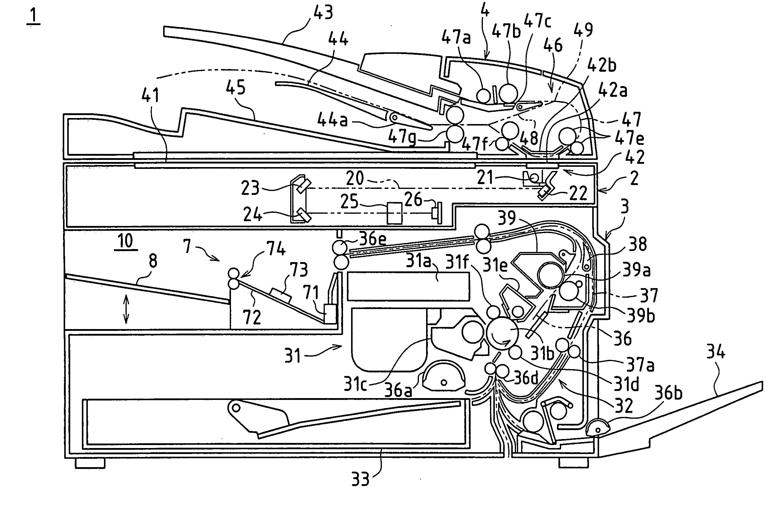
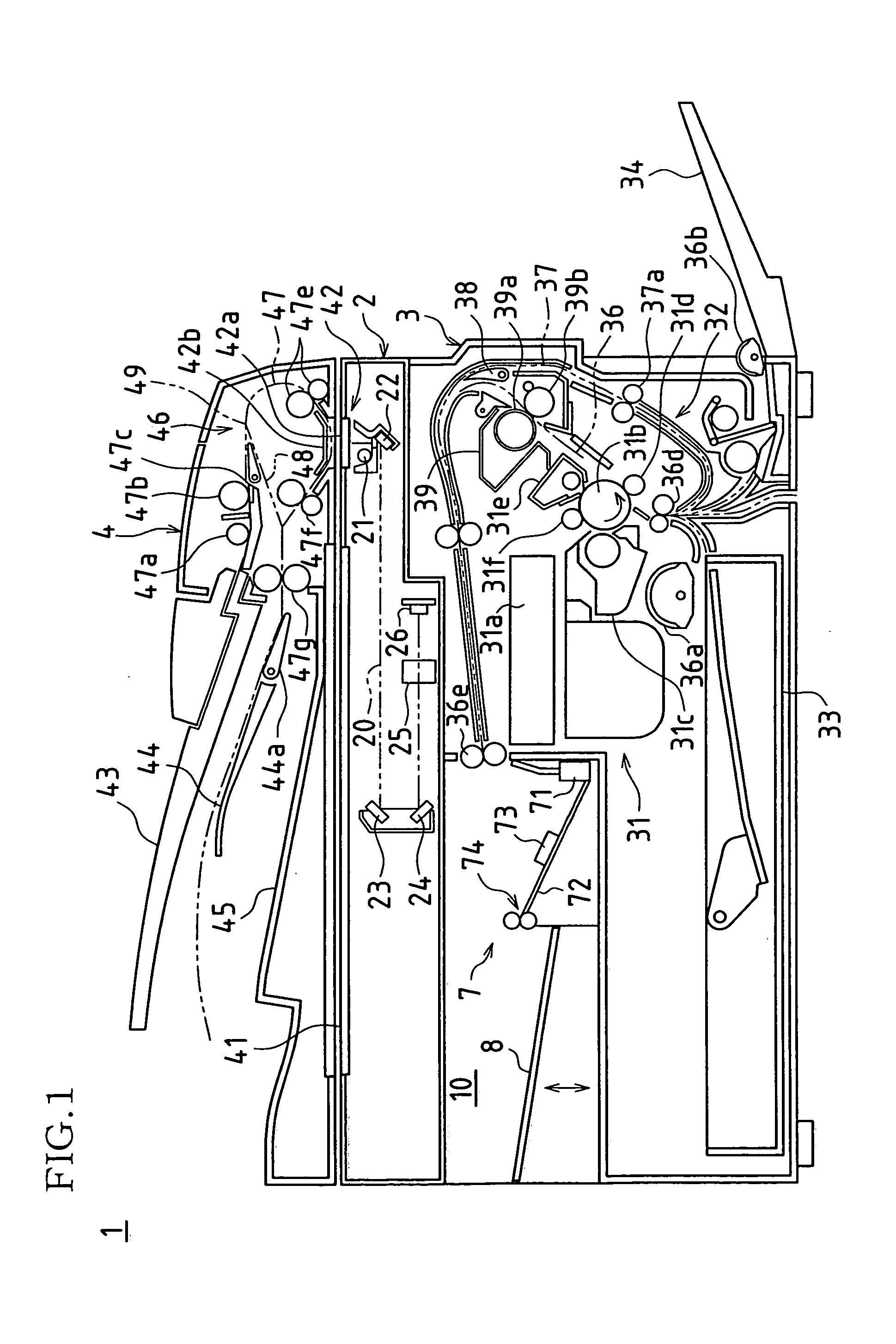
[0043] In the present embodiment, a case is explained in which an image forming apparatus provided with the paper post-processing apparatus of the present invention is applied in a multifunction machine. FIG. 1 shows an overview of the internal configuration of such a multifunction machine. A multifunction machine 1 is configured as an image forming apparatus using a built-up system. Specifically, the multifunction machine 1 has a configuration in which an original reading means is disposed in the upper portion of the apparatus main body, a feed means is disposed in the lower portion of the apparatus main body, and a print means is disposed between the original re...


PUM


Abstract

In an image forming apparatus in which a scanner portion is disposed in an upper portion of the apparatus, a paper cassette is disposed in a lower portion of the apparatus, and a print portion is disposed between the scanner portion and the paper cassette, in one embodiment, a paper post-processing portion that performs paper post-processing for paper transported from the apparatus main body after printing is disposed in a space of the apparatus main body formed by the scanner portion, the print portion, and the paper cassette. Provided in a discharge roller portion that discharges paper from the paper post-processing portion to a discharge tray are a drive roller, and a first idler roller and second idler roller that form a pair with the drive roller and can be selectively used when discharging paper to the discharge tray.

Description

CROSS REFERENCE TO RELATED APPLICATIONS [0001] This application claims priority under 35 U.S.C. § 119(a) on Patent Application No. 2005-11728 filed in Japan on Jan. 19, 2005, the entire contents of which are hereby incorporated by reference. BACKGROUND OF THE INVENTION [0002] 1. Field of the Invention [0003] The present invention relates to an image forming apparatus provided with a so-called inner finisher. [0004] 2. Related Art [0005] In recent years, development of apparatuses using front access systems and built-up systems as a part of compact design of image forming apparatuses has been advancing. [0006] In image forming apparatuses using a front access system, operation of an operating portion (also including a display portion), opening and closing of an opening / closing door, replenishment of paper in a feed portion, and extraction of paper from a discharge portion can all be performed from the front side of the apparatus. Also, such apparatuses are configured so that with the...

Claims


Application Information

Patent Timeline
Patent Type & Authority Applications(United States)
IPC IPC(8): G03G15/00
CPCG03G15/6538G03G15/6555G03G2215/00421
Inventor MATSUTOMO, YASUSHI
Owner SHARP KK
Why Eureka
Try Eureka