Articulated intramedullary nail
a technology of intramedullary nail and articulation, which is applied in the field of articulation intramedullary nail, can solve the problems of common joint wear and pain, chronic pain, and pain at the common site of joint wear and tear
- Summary
- Abstract
- Description
- Claims
- Application Information
AI Technical Summary
Benefits of technology
Problems solved by technology
Method used
Image
Examples
example 1
Articulated Nail with Inverted Arrangement of Joint Surfaces
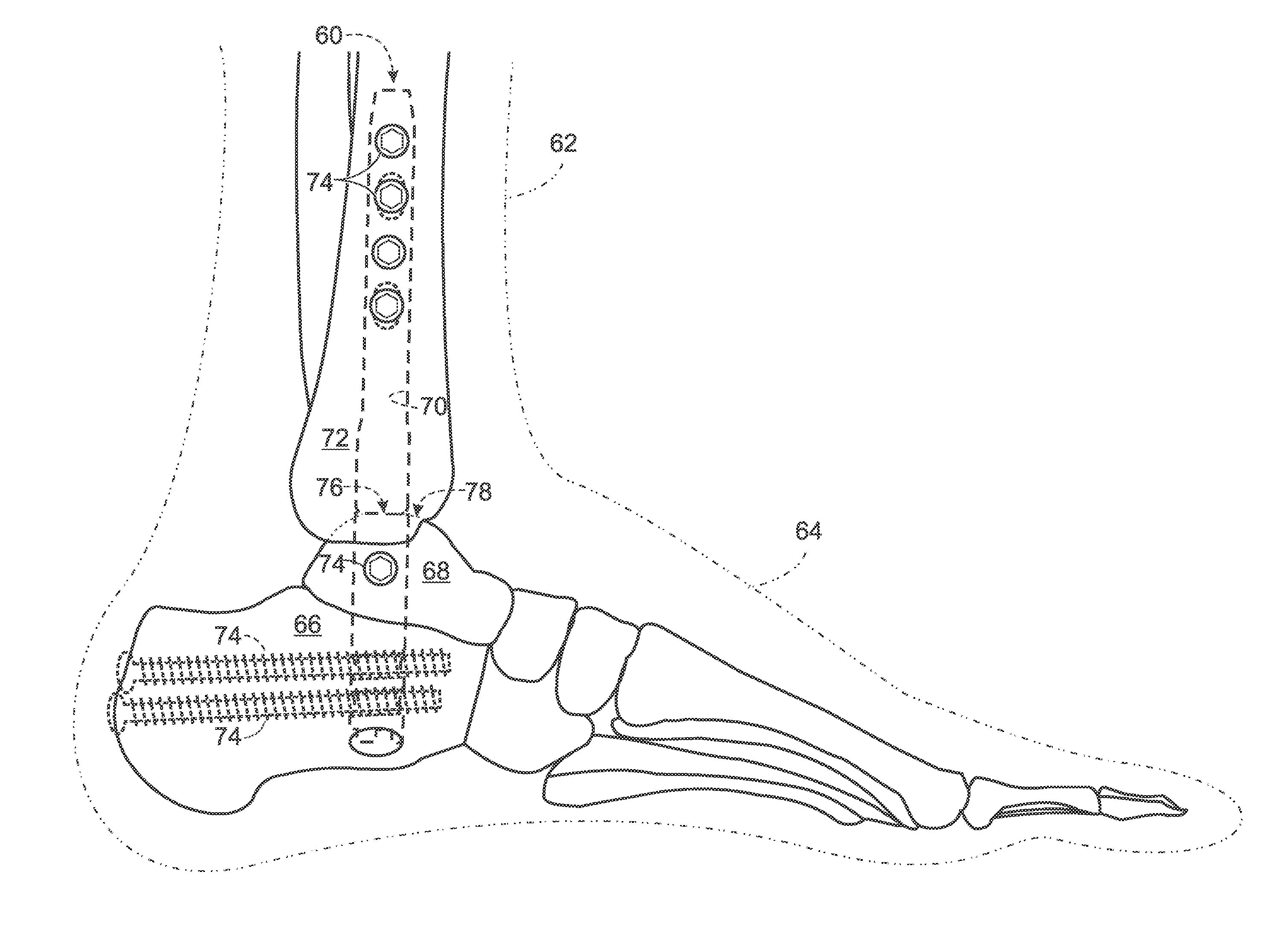
[0085]This example describes an exemplary articulated nail 240 with a generally inverted arrangement of joint surfaces with respect to nail 60 of FIGS. 1-8; see FIGS. 23-25.
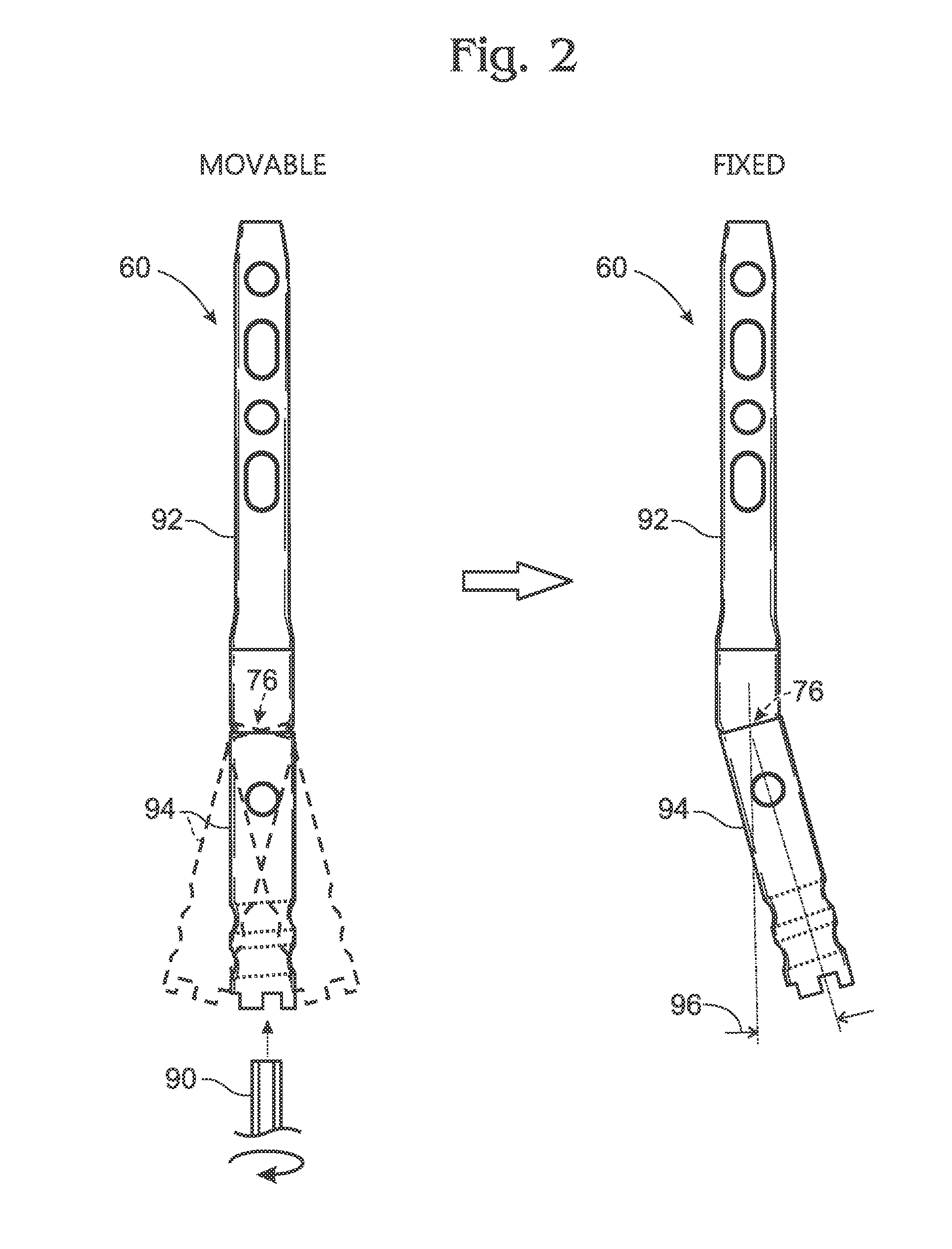
[0086]Nail 240 may be structured generally like nail 60. Accordingly, nail 240 may have a leading segment 92 attached to a trailing segment 94 via an adjustable joint 76 having movable and fixed configurations. A locking member 242 may be in threaded engagement with trailing segment 94 and may be turned to advance or retract the locking member, which adjusts the nail between locked and unlocked configurations.
[0087]However, nail 240 has noteworthy differences from nail 60. Locking member 242 does not have a spherical head that projects into a spherical cavity of leading segment 92 for capture therein (e.g., compare with FIGS. 7 and 8). Instead, leading segment 92 has a spanning member 244 that spans the adjustable joint. The spanning member has a spheric...
example 2
Articulated Nail with Deformable Locking Member
[0088]This example describes an exemplary articulated nail 260 having a locking member 262 that is deformable to place the nail in a fixed configuration; see FIGS. 26-28.
[0089]Nail 260 has structural similarity to nail 60 of FIGS. 1-8. For example, locking member 262 spans the adjustable joint and has a spherical head 264 that is captured in a cavity 266 defined at the trailing end of leading segment 92.
[0090]However, nail 260 has noteworthy differences from nail 60. Locking member 262 is composed of two discrete components, namely, an actuator 268 and an expandable member 270. The actuator is in threaded engagement with the expandable member and has a tapered nose 272 (see FIG. 27). The expandable member includes spherical head 264 (see FIG. 28), which is composed of integral sections that can be urged apart from one another by nose 272, which acts as a wedge when the actuator is advanced. Expansion of spherical head 264 produces frict...
example 3
Articulated Nails with Projections at the Joint Interface of the Nail
[0091]This example describes exemplary articulated nails 300, 310 having projections formed at the joint interface of the nail to resist slippage in the fixed configuration of the joint; see FIGS. 29, 30, and 30A.
[0092]FIGS. 29 and 30 show nail 300, which is a modified version of nail 60 (see FIGS. 1-8) having projections 312 formed on outer spherical surface region 124 of the nail. The projections may, for example, be prongs that slightly penetrate adjacent spherical surface region 122 of trailing segment 94 in response to compressive force generated by locking member 110 when the adjustable joint is locked to prevent pivotal motion.
[0093]Nail 310 is generally similar to nail 300 except that outer spherical surface region 124 has ribs 314 formed thereon.
PUM
 Abstract
Description
Claims
Application Information
 - R&D
- Intellectual Property
- Life Sciences
- Materials
- Tech Scout
- Unparalleled Data Quality
- Higher Quality Content
- 60% Fewer Hallucinations
Browse by: Latest US Patents, China's latest patents, Technical Efficacy Thesaurus, Application Domain, Technology Topic, Popular Technical Reports.
© 2025 PatSnap. All rights reserved.Legal|Privacy policy|Modern Slavery Act Transparency Statement|Sitemap|About US| Contact US: help@patsnap.com


