Wireless communication system, base station device, and terminal device

a wireless communication system and base station technology, applied in the field of wireless communication systems, can solve the problems of increasing performance degradation, limited number of receive antennas that can be arranged in the mobile station device, and marked degradation of spatial filtering performance, so as to improve the frequency utilization efficiency of the wireless communication system

Active Publication Date: 2013-12-19
SHARP KK
View PDF2 Cites 144 Cited by
  • Summary
  • Abstract
  • Description
  • Claims
  • Application Information

AI Technical Summary

Benefits of technology

[0082]With the invention, even in case of the MIMO transmission using the LR technology in the spatial demultiplexing processing, the different modulation schemes can be u

Problems solved by technology

However, the number of receive antennas that can be arranged in the mobile station device is limited.
However, the spatial filtering has a spatial demultiplexing performance which is markedly degraded as compared with maximum likelihood detect

Method used


Image

  • Wireless communication system, base station device, and terminal device
  • Wireless communication system, base station device, and terminal device
  • Wireless communication system, base station device, and terminal device

Examples


first embodiment

2. First Embodiment

[0152]A first embodiment, to which the invention is applied, is aimed at MIMO spatial multiplexing transmission in which a base station device including Nt transmit antennas and a terminal device including Nr receive antennas make communication.

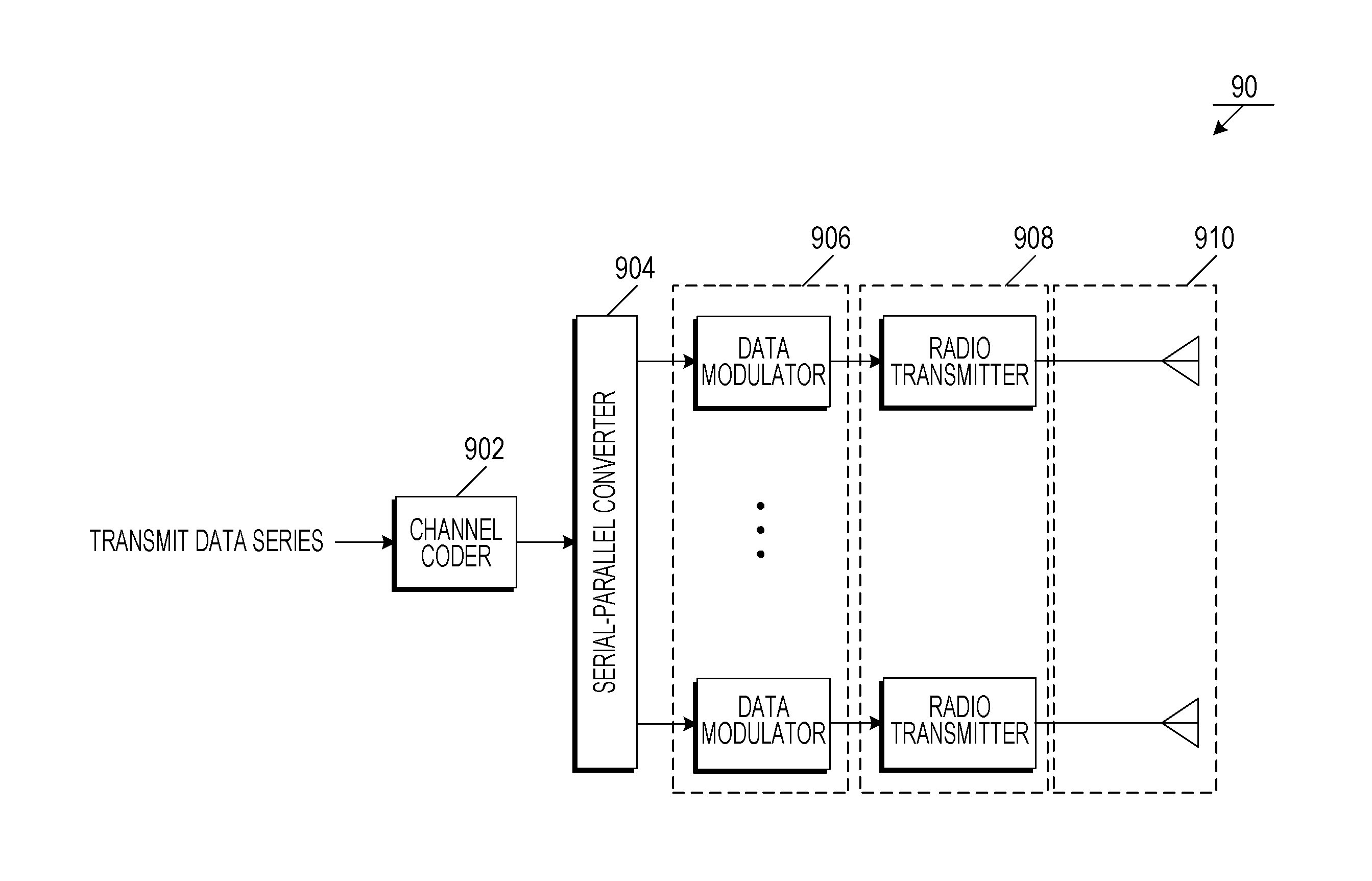
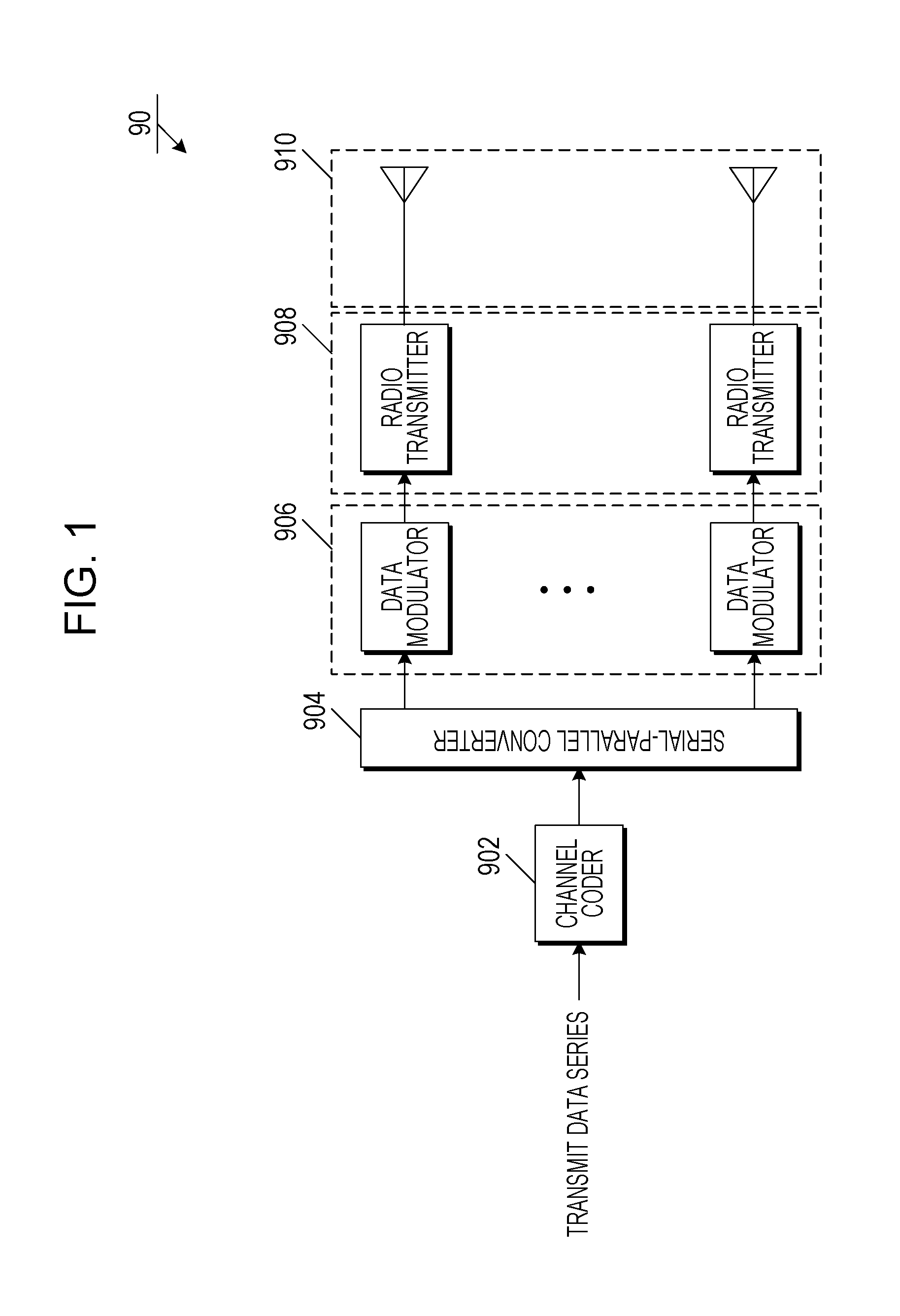
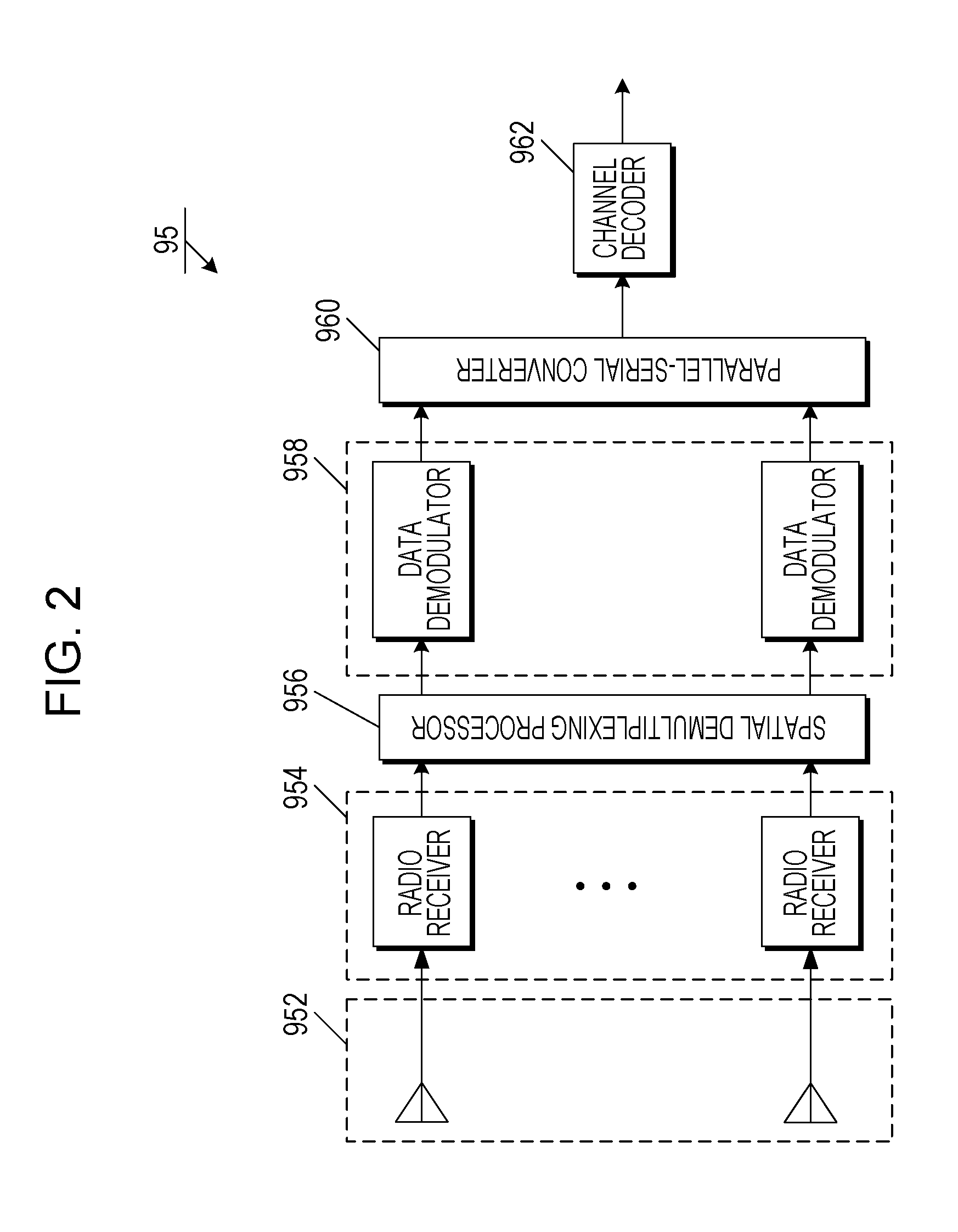
[0153]Here, FIG. 10 is a block diagram showing a configuration of a base station device 10. FIG. 11 is a block diagram showing a configuration of a terminal device 20. It is assumed that a transmitter (a base station device) transmits R data streams to a receiver (a terminal device). R has to satisfy min(Nt, Nr)≧R. Description is given below based on R=Nt=Nr.

[0154]FIG. 10 is an illustration showing the configuration of the base station device 10, and includes a channel coder 110, a serial-parallel converter 120, data modulators 130, radio transmitters 140, and antennas 150. Also, FIG. 11 is an illustration showing the configuration of the terminal device 20, and includes antennas 210, radio receivers 220, a spatial demultip...

second embodiment

3. Second Embodiment

[0176]The first embodiment is aimed at the MIMO transmission between the base station device including the plurality of transmit antennas and the terminal device including the plurality of receive antennas by one-to-one correspondence. Such MIMO transmission is called single user MIMO (SU-MIMO) transmission.

[0177]Meanwhile, the maximum frequency utilization efficiency that can be provided by the MIMO transmission is proportional to a smaller value of the Nt transmit antennas and the Nr receive antennas included in the wireless system. However, since the number of antennas that can be arranged in the terminal device is limited, the frequency utilization efficiency that can be achieved by the SU-MIMO transmission is also limited.

[0178]Owing to this, multi-user MIMO (MU-MIMO) transmission is becoming popular, in which the MIMO transmission is performed while a plurality of terminal devices are assumed as a large-scale antenna array. In the downlink MU-MIMO transmiss...

third embodiment

4. Third Embodiment

[0226]The second embodiment has been aimed at the downlink MU-MIMO transmission that performs the precoding based on the LR technology in the base station device, and the method of applying the adaptive modulation technology that applies the different modulation schemes for the respective users has been disclosed. In the downlink MU-MIMO, the modulation scheme has to be changed so that the base station device can properly perform the modulo arithmetic that restricts an increase in transmit power.

[0227]In the third embodiment, a method of allowing the adaptive modulation technology to be performed in the downlink MU-MIMO transmission that performs the precoding based on the LR technology, by a data modulation method different from the method targeted in any of the first and second embodiments.

[0228]In the third embodiment, like the second embodiment, it is considered that U terminal devices 23 each having one receive antenna are connected with a base station device...


PUM


Abstract

A terminal device notifies a base station device about control information associated with a receive quality of the terminal device. The base station device performs data modulation on a plurality of pieces of transmit data for the terminal device, by using a plurality of different data modulation schemes one by one, based on the control information, and spatially multiplexes the plurality of pieces of transmit data after the data modulation over a single wireless resource and transmits a spatially multiplexed signal. The terminal device receives the signal with the plurality of pieces of transmit data spatially multiplexed, and detects desirable transmit data from the receive signal, based on a first channel matrix which represents channel state information between the base station device and the terminal device and a second channel matrix in which the first channel matrix is multiplied by a transform matrix. Accordingly, an adaptive modulation technology is applied even to MIMO spatial multiplexing transmission using a LR technology, and hence a wireless communication system and so forth that can contribute to improvement in frequency utilization efficiency can be provided.

Description

TECHNICAL FIELD[0001]The present invention relates to a wireless communication system and so forth.BACKGROUND ART[0002]In long term evolution (LTE), which has been standardized in the 3rd generation partnership project (3GPP) and has served as the 3.9-generation radio transmission scheme, a multiple input multiple output (MIMO) technology that performs radio transmission by using a plurality of transmit and receive antennas has been specified for markedly increasing a frequency utilization efficiency as compared with 3rd generation radio transmission schemes.[0003]A spatial multiplexing (SM) technology, which is one of MIMO technologies, can realize an increase in transmission speed without expansion in frequency bandwidth. Also, LTE-advanced (LTE-A), which is an extension of LTE, has been approved as one of 4th generation radio transmission schemes by International Telecommunication Union Radiocommunications Sector (ITU-R), and standardization of LTE-A is actively promoted. In LTE-...

Claims


Application Information

Patent Timeline
IPC IPC(8): H04B7/04
CPCH04B7/0482H04L1/0003H04B7/0697H04B7/0465H04B7/0452H04B7/0632
Inventor TOMEBA, HIROMICHIONODERA, TAKASHINAKANO, HIROSHIRUIZ DELGADO, ALVAROTO, SHIMPEI
Owner SHARP KK
Why Eureka
Try Eureka