Body lumen junction localization

a lumen junction and localization technology, applied in the field of body lumen junction localization, can solve the problems of decreasing the tools required for proper positioning, ablation of the junction and targeted tissue, and achieve the effect of increasing spatial resolution and decreasing the number of tools required

Active Publication Date: 2013-12-19
3DT HLDG
View PDF6 Cites 37 Cited by
  • Summary
  • Abstract
  • Description
  • Claims
  • Application Information

AI Technical Summary

Benefits of technology

[0012]Various embodiments of devices, systems, and methods for localization of body lumen junctures are disclosed herein. At least some of the disclosed embodiments allow a clinician to identify a body lumen junction, such as a pulmonary vein-atrial junction, or other desired anatomical structures, to a higher spatial resolution than with conventional techniques. Thus, subsequent ablation may be performed using the same device that presented a visual signal of the junction, thereby decreasing the tools required for proper location and ablation of the junction and targeted tissue.

Problems solved by technology

Thus, subsequent ablation may be performed using the same device that presented a visual signal of the junction, thereby decreasing the tools required for proper location and ablation of the junction and targeted tissue.

Method used


Image

  • Body lumen junction localization
  • Body lumen junction localization
  • Body lumen junction localization

Examples


Embodiment Construction

[0043]It will be appreciated by those of skill in the art that the following detailed description of the disclosed embodiments is merely exemplary in nature and is not intended to limit the scope of the appended claims.

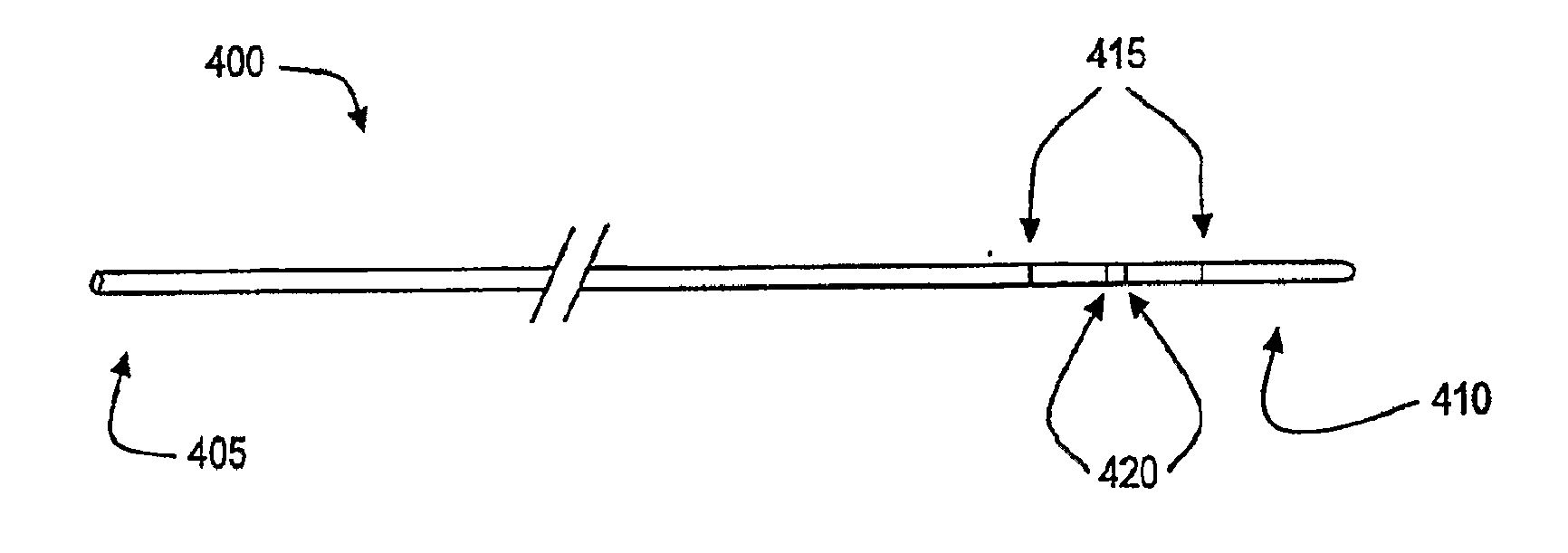
[0044]During various medical procedures involving intraluminal insertion of catheters or other devices, proper navigation of the device through body lumens, such as blood vessels or the heart, is critical to the success of the procedure. Indeed, unless the tissue targeted for treatment or diagnosis during the procedure is properly located, the procedure can be ineffective or, even worse, damaging to nearby healthy tissue. Therefore, a number of the embodiments disclosed herein permit a clinician to readily locate a catheter, such as an ablation catheter, or other medical device within a body lumen in relation to body lumen junctions or other anatomical structures within the lumen. This leads to proper localization of targeted tissue and increased favorable outcomes.

[0...


PUM


Abstract

Devices, systems, and methods for the localization of body lumen junctions and other intraluminal structure are disclosed. Various embodiments permit clinicians to identify the locations of intraluminal structures and medical devices during non-surgical medical techniques, such as cardiac ablation, by determining the intralumen conductance and/or cross-sectional area at a plurality of locations within the body lumen

Description

PRIORITY[0001]The present application is related to, claims the priority benefit of, and is a continuation application of, U.S. patent application Ser. No. 12 / 305,520, filed Dec. 18, 2008, which is related to, claims the priority benefit of, and is a §371 application of, International Patent Application Serial No. PCT / US2007 / 015239, filed Jun. 29, 2007, which claims priority to U.S. Provisional Patent Application Ser. No. 60 / 817,422, filed Jun. 30, 2006, and which also claims priority to and is a continuation-in-part of U.S. patent application Ser. No. 11 / 063,836, filed Feb. 23, 2005, which claims priority to U.S. patent application Ser. No. 10 / 782,149, filed Feb. 19, 2004, issued as U.S. Pat. No. 7,454,244, which claims priority to U.S. Provisional Patent Application Ser. No. 60 / 449,266, filed Feb. 21, 2003, U.S. Provisional Patent Application Ser. No. 60 / 493,145, filed Aug. 7, 2003, and U.S. Provisional Patent Application Ser. No. 60 / 502,139, filed Sep. 11, 2003. The contents of e...

Claims


Application Information

Patent Timeline
Patent Type & Authority Applications(United States)
IPC IPC(8): A61B5/06A61B5/00A61B18/00A61B5/053
CPCA61B5/068A61B5/0538A61B5/6853A61B18/00A61B5/1077A61B18/1492A61B2018/00404A61B2018/00541A61B2018/00875A61B2018/0212
Inventor KASSAB, GHASSAN S.
Owner 3DT HLDG
Why Eureka
Try Eureka