Operation display device of chassis dynamometer system

a display device and dynamometer technology, which is applied in the direction of vehicle testing, structural/machine measurement, instruments, etc., can solve the problems of difficult to confirm whether or not the vehicle type of the test vehicle is the vehicle type, the operator cannot confirm whether or not the operating status of the roller is not available, and the visual confirmation cannot be readily achieved

Active Publication Date: 2013-12-19
MEIDENSHA ELECTRIC MFG CO LTD
View PDF7 Cites 16 Cited by
  • Summary
  • Abstract
  • Description
  • Claims
  • Application Information

AI Technical Summary

Benefits of technology

[0007]When fuel consumption or exhaust gas is measured using a chassis dynamometer, a chassis dynamometer inherent to each vehicle type can be basically used as a testing device. In such a case, for such a reason that a large number of test facilities are necessary, the test is carried out by varying combination of the rollers of a four-wheel drive vehicle chassis dynamometer which are to be used. On the other hand, upon measuring fuel consumption or exhaust gas, generally, a place (a test cell) in which the rollers of the chassis dynamometer are set and a position in which a console for the test is set are individually provided in separate rooms in consideration of working circumstances such as safety of an operator, noise, etc. Therefore, there occurs a problem that on the side of the console, the operator cannot confirm whether or not an operating status of the rollers to be actually operated is conformed to the vehicle type of the test

Problems solved by technology

Therefore, there occurs a problem that on the side of the console, the operator cannot confirm whether or not an operating status of the rollers to be actually operated is conformed to the vehicle type of the test vehicle.
Further, even when the console and the chassis dynamometer are set in the same room, the rollers of the chassis dynamometer are placed within a pit (underground), and tires of the vehicle are occasionally surrounded by a safety fence, so that visual confirmation cannot be readily

Method used


Image

  • Operation display device of chassis dynamometer system
  • Operation display device of chassis dynamometer system
  • Operation display device of chassis dynamometer system

Examples


Embodiment Construction

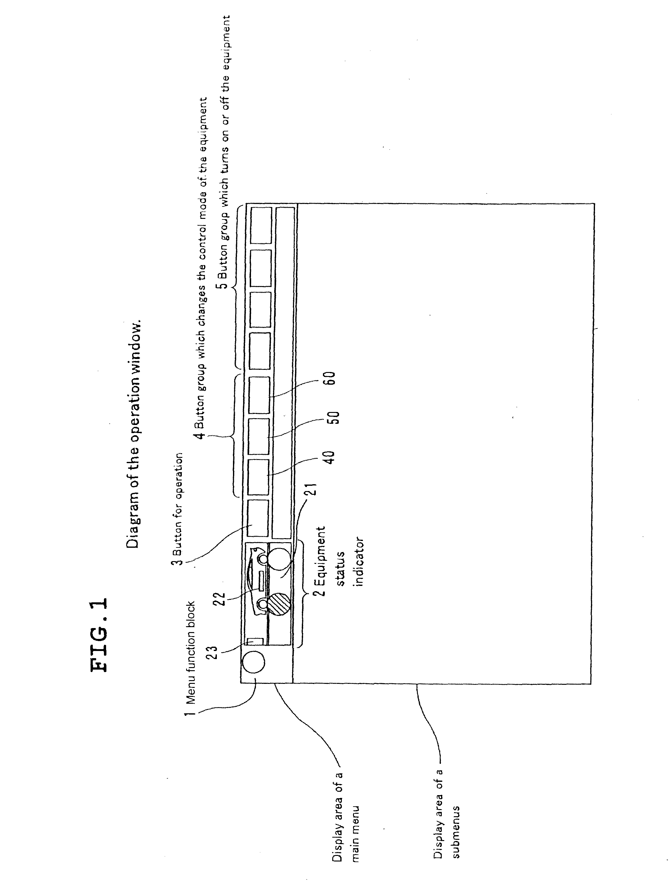
[0020]FIG. 1 shows an example of an operation window in an operation display portion provided on a console as an operation display device according to the present invention. In FIG. 1, a main menu display area in the operation window includes a menu function block 1, a status indicating function block 2 that indicates a status of equipments of a chassis dynamometer, an operation lock function block 3, a mode setting function button group 4 and an equipment on / off changeover function button group 5. These function blocks and function button groups are selected with a mouse-click or a touch-panel operation.

[0021]The menu function block 1 includes callers for various items such as vehicle type ID, alarm setting, maintenance setting, warm-up setting and measuring monitor display, although not shown.

[0022]The status indicating function block 2 is a block configured to indicate a setting status of the chassis dynamometer as currently set. The status indicating function block 2 includes an...


PUM


Abstract

There is a demand for enhancement of operability when a change of combination of rollers of a chassis dynamometer and the dynamometer is set depending upon a vehicle type of a test vehicle. A status indicating function block that indicates an equipment construction is disposed in a main menu display area that is provided on a console. With this arrangement, a current test status can be recognized. Further, a vehicle type selection window calling function block is disposed in a mode setting function button group in the main menu display area. A vehicle type selection window called by the vehicle type selection window calling function block includes a roller selection section to select rollers corresponding to the test vehicle, a setting display section that indicates a current setting equipment construction, and a setting display section that indicates a setting equipment construction during change of the setting.

Description

TECHNICAL FIELD [0001]The present invention relates to an operation display device of a chassis dynamometer system, and particularly relates to a display device having an operation window based on a vehicle type of a test vehicle, or the like.BACKGROUND ART [0002]FIG. 5 is a diagram showing a schematic configuration of a chassis dynamometer system. Reference sign Rf denotes a roller for a front wheel of a test vehicle on which the front wheel is set. Reference sign Rr denotes a roller for a rear wheel of the test vehicle on which the rear wheel is loaded. A dynamometer (not shown) as a load is coupled to each of the rollers (Rf, Rr) for the front and rear wheels. Reference signs IV1, IV2 denote inverter boards through which each of the dynamometers is controlled on the basis of a predetermined set value, a speed signal detected by a speed detector Sd and the like. Reference sign PLC denotes a switchgear panel through which on / off control of switchgear for turning on or off a power s...

Claims


Application Information

Patent Timeline
IPC IPC(8): G06F3/0482
CPCG06F3/0482G01M17/0072G01M17/007G01L3/24G01M15/044G06F3/0481
Inventor WATANABE, KENJIMANEKI, YUKIMASA
Owner MEIDENSHA ELECTRIC MFG CO LTD
Why Eureka
Try Eureka