Ice bar system

a bar system and ice bar technology, applied in the field of ice bar systems, can solve the problems of no single method presenting a consistently effective, efficient and economical system, and the content of glasses and bottles positioned on the bar top tends to lose their chill, and eventually become room temperatur

Inactive Publication Date: 2013-12-26
BUSH REFRIGERATION
View PDF4 Cites 16 Cited by
  • Summary
  • Abstract
  • Description
  • Claims
  • Application Information

AI Technical Summary

Benefits of technology

[0003]It is the object of the present invention to provide an ice bar system which is easily installed as a new bar top or retro-fitted into an existing bar.
[0004]It is another object of the present invention to provide an ice bar system which efficiently and effectively maintains the cold temperature of glasses, bottles, and other drinks placed on a bar top.
[0005]It is a further object of the present invention to provide an ice bar system in which solid ice is effectively utilized as a bar top, the ice being easily formed, maintained, and then melted and removed for cleaning or other purposes when the system is no longer required.

Problems solved by technology

However, the contents of glasses and bottles positioned on the bar top tend to lose their chill and, if nursed long enough, will eventually become room temperature.
While attempts have been made to keep such drinks cold, e.g. from placing drinks in ice on bar top surfaces to trying to refrigerate surfaces themselves, no single method presents a consistently effective, efficient, and economical system for accomplishing this objective, and there are none which can readily be installed in new bars and retro-fitted into existing ones.

Method used


Image

  • Ice bar system
  • Ice bar system
  • Ice bar system

Examples


Embodiment Construction

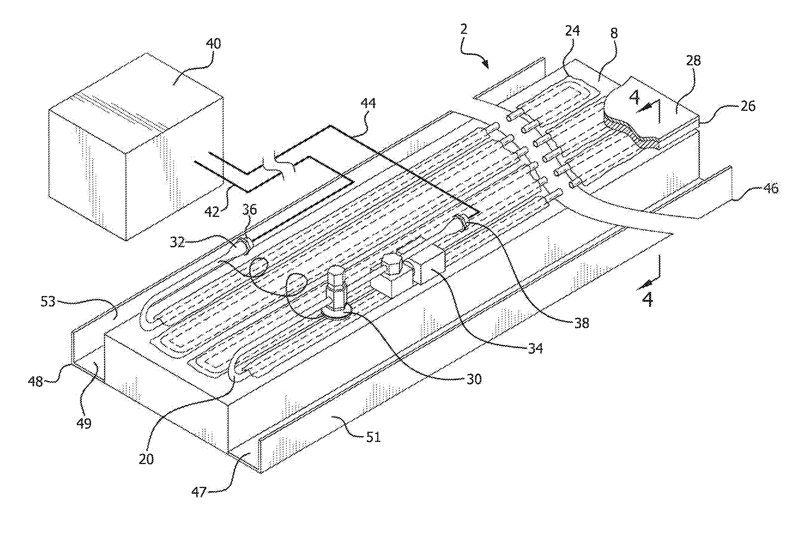
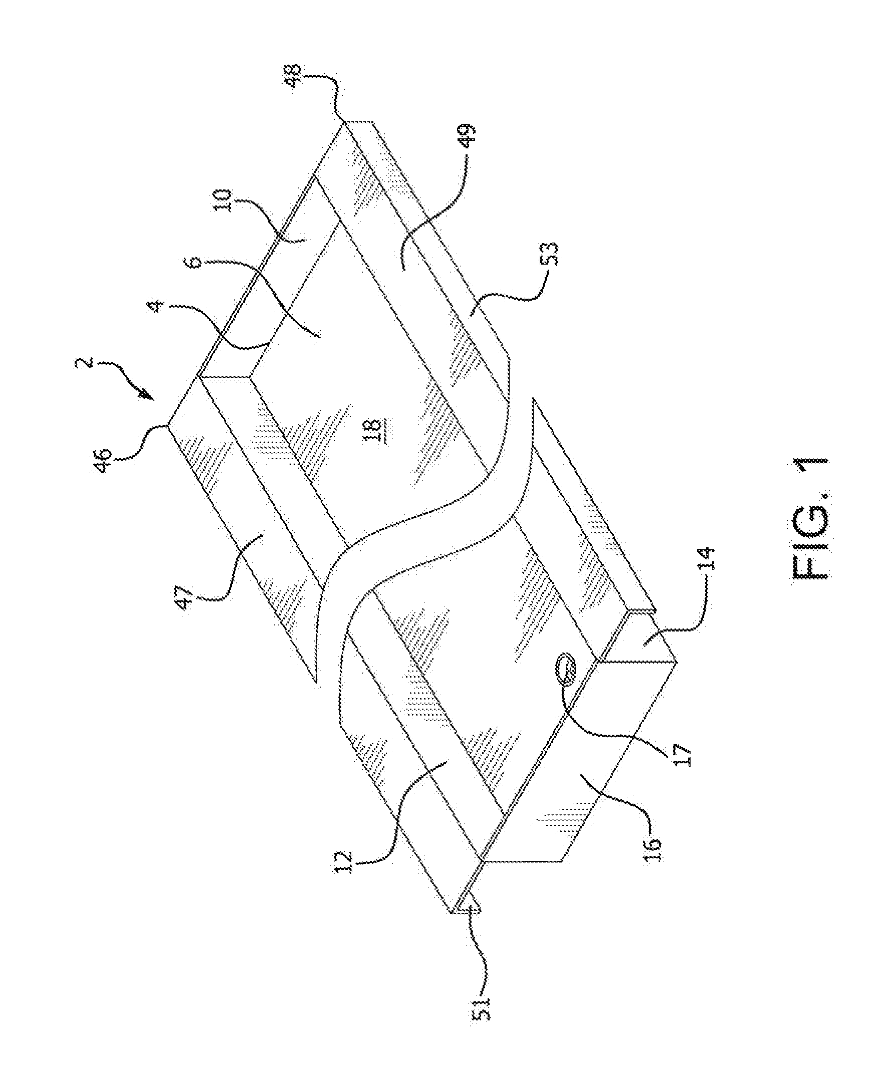
[0014]The ice bar system of the present invention comprises ice bar unit 2 of given length having floor member 4 with top surface 6 and bottom surface 8, each extending the length of the ice bar unit. Front wall 10, lateral walls 12 and 14, and rear wall 16 extend up from and circumscribe top surface 6 of floor member 4. Sunken well 18 creating a reservoir for containing water and ice is formed over top surface 6 and within front, lateral, and rear walls 10, 12, 14, and 16. Drain 17 is provided within floor member 4.

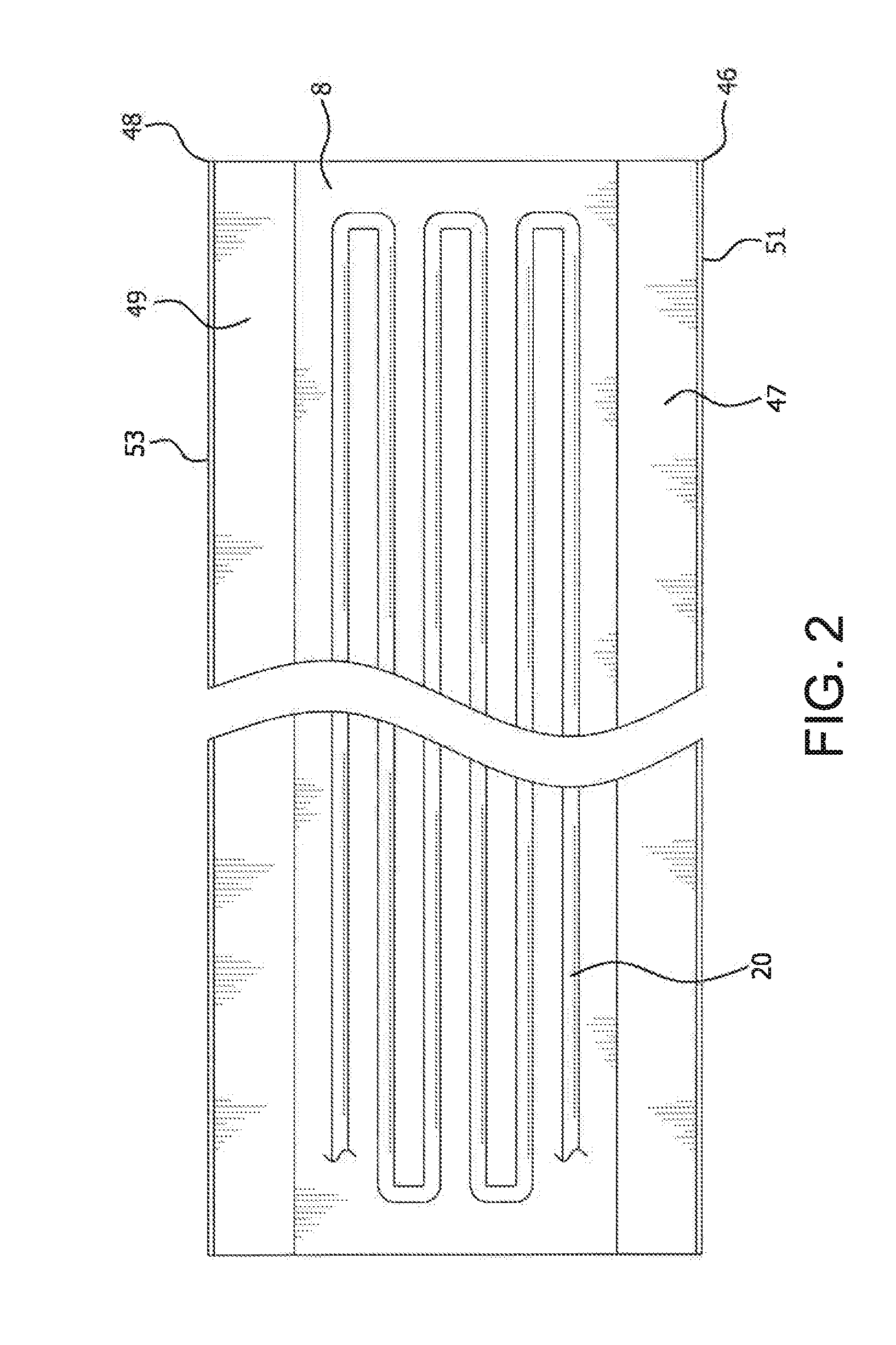
[0015]Ice bar unit 2 further comprises a series of switchback coils 20 extending substantially the length of bottom. surface 8 of floor member 4. Coils 20 are filled with refrigerant 21 and are located immediately adjacent to and beneath bottom surface 8 of floor member 4. Coils 20 are secured to bottom surface 8 by thermal mastic adhesive 22 and aluminum foil tape 24. A layer of elastomeric pipe insulation 26 and a layer of polystyrene board 28 cover the entire length o...


PUM


Abstract

An ice bar system utilizes an ice bar unit having a sunken well or reservoir circumscribed by a floor member and front, rear, and lateral walls upstanding from the floor member. Refrigerant filled coils located beneath the surface of the floor member are utilized, via a compressor system, to create a solid block of ice within the reservoir, after it is filled with water. The ice bar unit also has mounting brackets which extend outwardly from its lateral walls, each mounting bracket has horizontal and vertical members which frame the ice bar unit, the horizontal member also being conveniently available as arm rests for bar patrons.

Description

BACKGROUND OF THE INVENTION[0001]Bars, pubs, many restaurants and various other eating and drinking establishments have a designated bar area, with a bar top, in which drinks are served and at which patrons sit and stand. Drinks, cocktails, and beer served up on tap or in bottles or mugs at these places are routinely served cold to the patron. However, the contents of glasses and bottles positioned on the bar top tend to lose their chill and, if nursed long enough, will eventually become room temperature. While attempts have been made to keep such drinks cold, e.g. from placing drinks in ice on bar top surfaces to trying to refrigerate surfaces themselves, no single method presents a consistently effective, efficient, and economical system for accomplishing this objective, and there are none which can readily be installed in new bars and retro-fitted into existing ones.SUMMARY OF THE INVENTION[0002]It is thus the object of the present invention to provide an ice bar system which ove...

Claims


Application Information

Patent Timeline
Patent Type & Authority Applications(United States)
IPC IPC(8): F25C1/04
CPCF25C1/04A47F3/0439A47F9/00
Inventor BUSH, JEFFREY L.KERBER, JEFFREY G.
Owner BUSH REFRIGERATION
Why Eureka
Try Eureka