Chromatography column stand

Active Publication Date: 2013-12-26
CYTIVA SWEDEN AB
View PDF9 Cites 2 Cited by
  • Summary
  • Abstract
  • Description
  • Claims
  • Application Information

AI Technical Summary

Benefits of technology

[0008]Hereby, the top end cell could be rotated such that the filter, net and distribution means will be kept together by gravitational force which will simplify disassembly of the different parts. The different parts and fasteners

Problems solved by technology

A common problem during maintenance of chromatography columns is disassembly and assembly of parts.
Maintenance and replacement of

Method used


Image

  • Chromatography column stand
  • Chromatography column stand
  • Chromatography column stand

Examples


Example

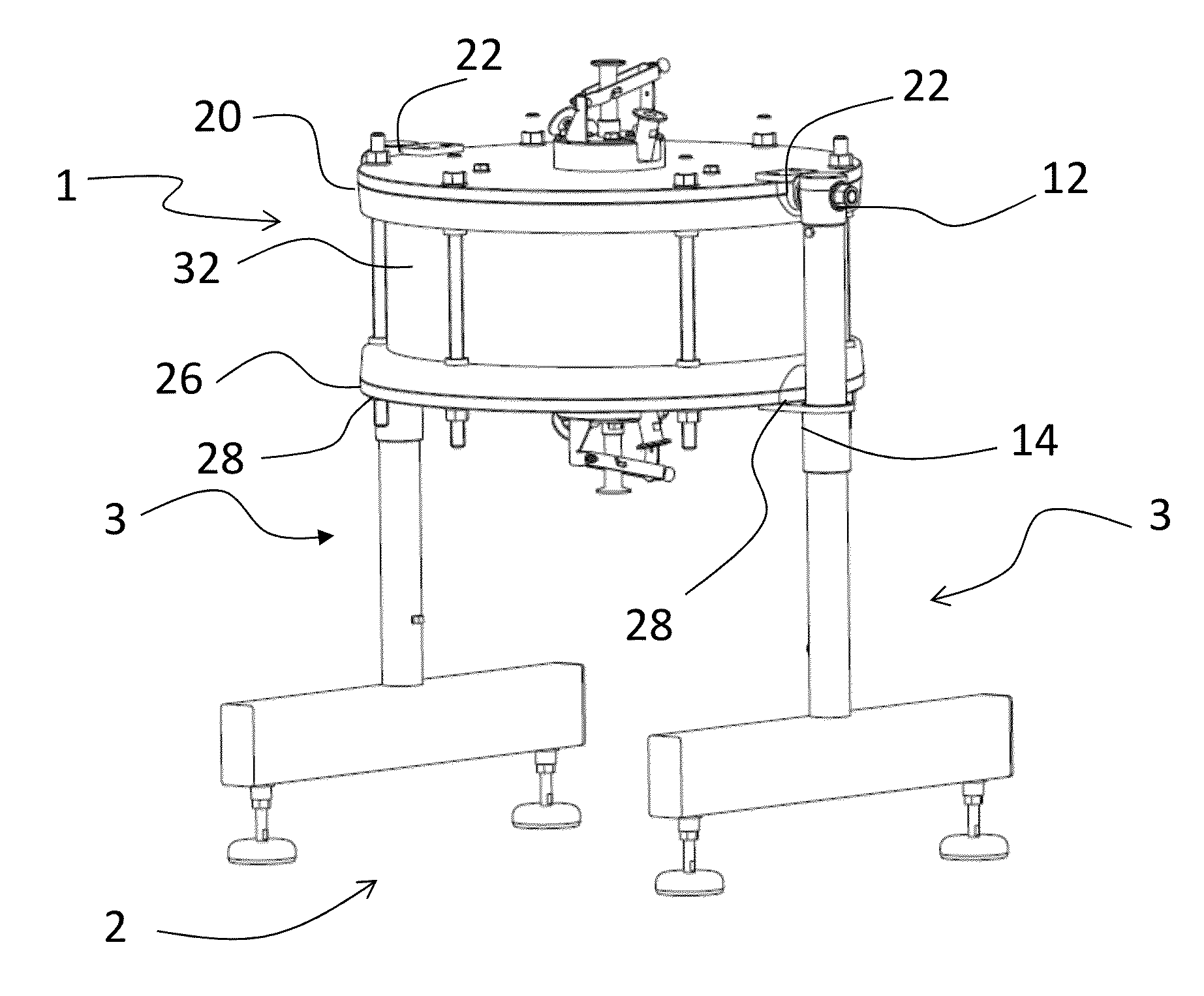
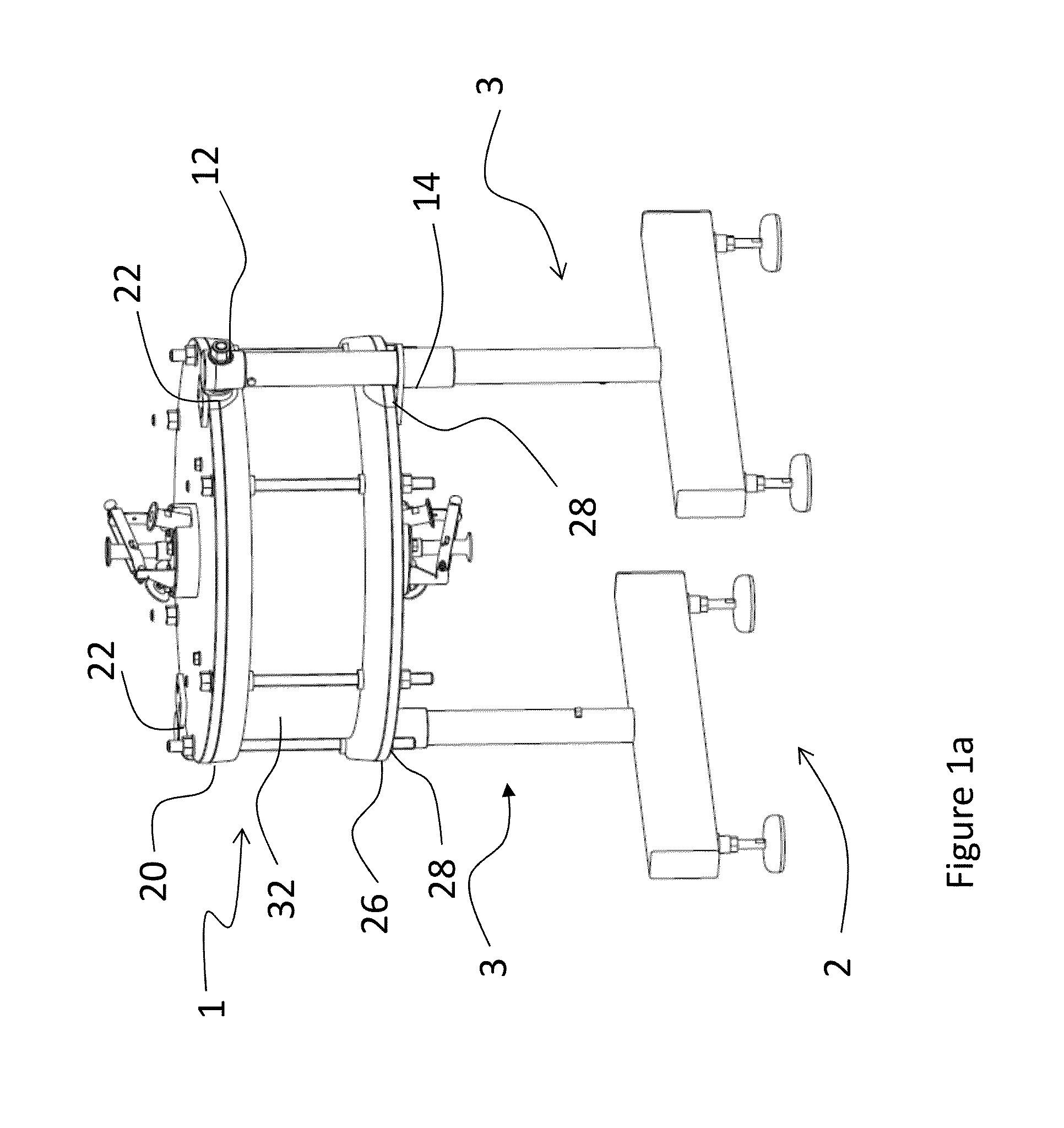
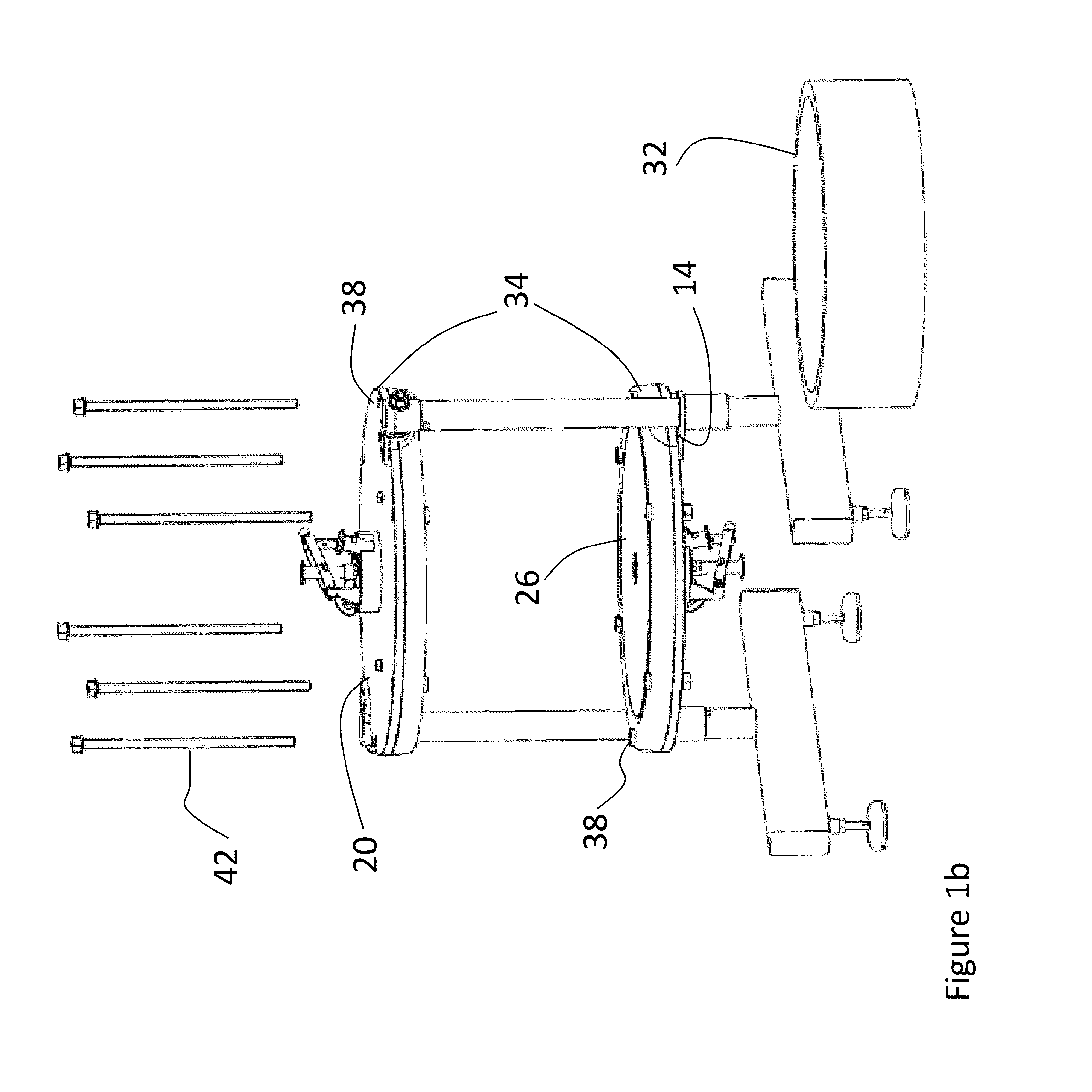
[0017]FIGS. 1a-1d show one embodiment of a chromatography column 1 and a stand 2 according to the invention. FIG. 1a shows the chromatography column 1 in an assembled position provided on the stand 2. FIG. 1b shows the same chromatography column as in FIG. 1a but disassembled. In this embodiment the stand 2 comprises two identical legs 3, also shown in FIG. 2. The legs 3 comprise one vertically oriented rod 4, which in its lower end 6 is fastened to the middle part of a horizontally oriented rod 8. The horizontally oriented rod 8 is adapted to rest on the ground via two feet 10 positioned one in each end of the horizontally oriented rod 8. Furthermore the vertically oriented rod 4 comprises a rotatable upper fastening means 12 and a lower fastening means 14 positioned below the upper fastening means 12, i.e. closer to the lower end 6 of the vertically oriented rod 4. The lower fastening means 14 can be adjusted vertically along the vertically oriented rod 4.

[0018]Now referring to FI...


PUM

PropertyMeasurementUnit
Angleaaaaaaaaaa

Abstract

A method for conducting maintenance on a chromatography column (1; 51), said column comprising a column tube (32), a top end cell (20) and a bottom end cell (26), where during chromatography said column tube (32) is secured between said top end cell (20) and said bottom end cell (26). Said method comprises the step of rotating at least the top end cell (20) 180 degrees around a horizontal axis before maintenance is conducted to the top end cell (20).

Description

FIELD OF THE INVENTION[0001]The present invention relates to a stand for holding a chromatography column and to a method for conducting maintenance to a chromatography column.BACKGROUND OF THE INVENTION[0002]Chromatography columns are typically comprised of a column tube with a top end cell covering the top opening of the tube and a bottom end cell covering the bottom opening of the tube. A chromatography column with variable column height also comprises a plunger or adaptor integrated in the top end cell, which adaptor can be moved to different heights within the column tube. The top end cell (possibly integrated with an adaptor) and bottom end cell comprise further sample inlet / outlet, sample distribution means, filter, net, O-rings and seals. Filters, nets, distribution means, O-rings and seals may need to be replaced or cleaned after some time. A common problem during maintenance of chromatography columns is disassembly and assembly of parts. Due to the heavy parts of large chro...

Claims


Application Information

Patent Timeline
IPC IPC(8): B01D65/00B23P6/00
CPCB01D15/08B01D15/22G01N30/56G01N30/6017G01N30/6047Y10T29/49718
Inventor USELIUS, PERDAMBULEFF, KYRILDAVIS, JOHN
Owner CYTIVA SWEDEN AB
Why Eureka
Try Eureka