Lotion applicator with adjustable handle

Active Publication Date: 2015-09-01
HUDSON WILLIAM RUSSELL
View PDF14 Cites 10 Cited by
  • Summary
  • Abstract
  • Description
  • Claims
  • Application Information

AI Technical Summary

Benefits of technology

[0006]It is therefore an object of the present invention to provide a lotion applicator that allows a user to more easily access all areas of the body.
[0007]I

Problems solved by technology

Applying lotions to certain areas of the body can be difficult and challenging.
However, the elderly or those who are otherwise inflexible are unable to reach certain areas of the

Method used


Image

  • Lotion applicator with adjustable handle
  • Lotion applicator with adjustable handle
  • Lotion applicator with adjustable handle

Examples


Example

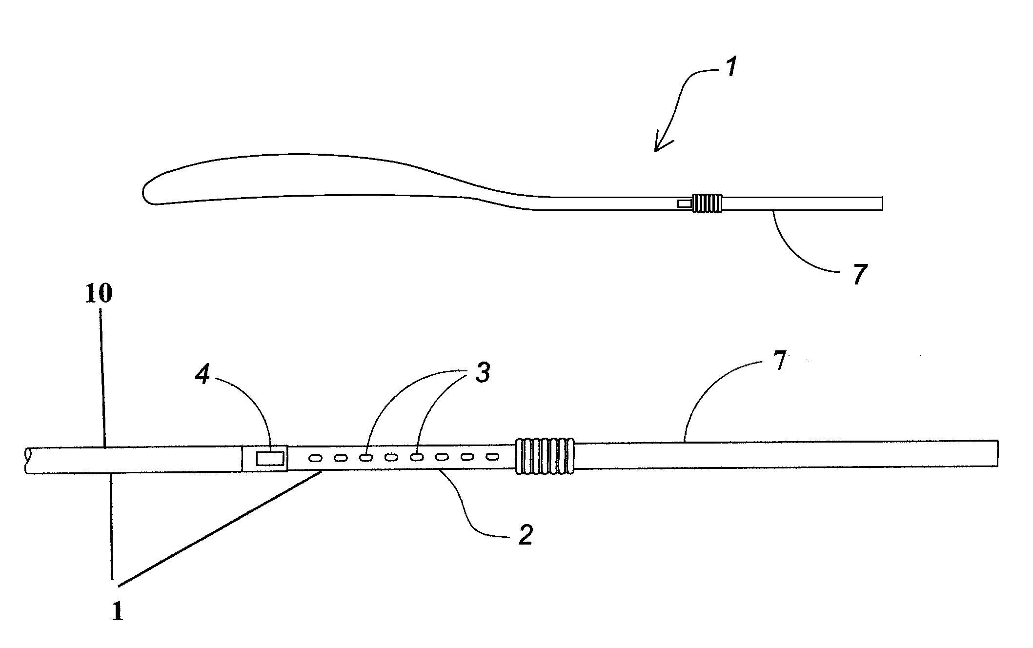
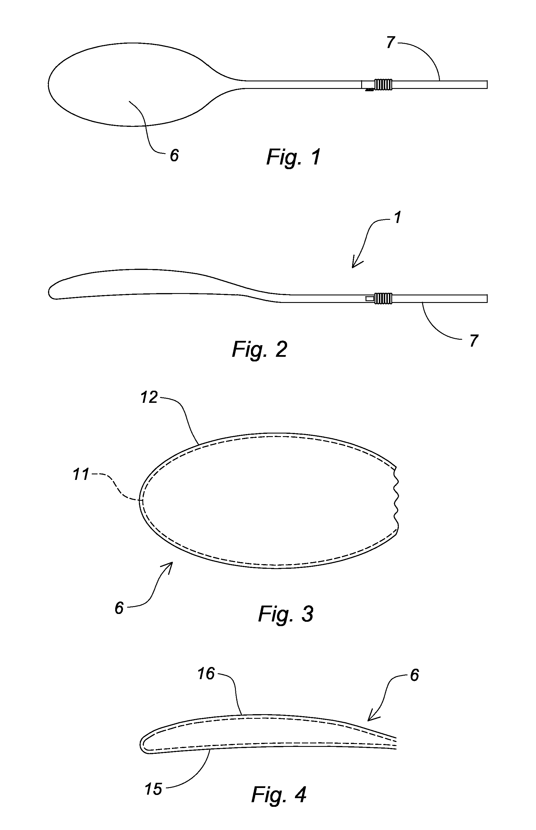
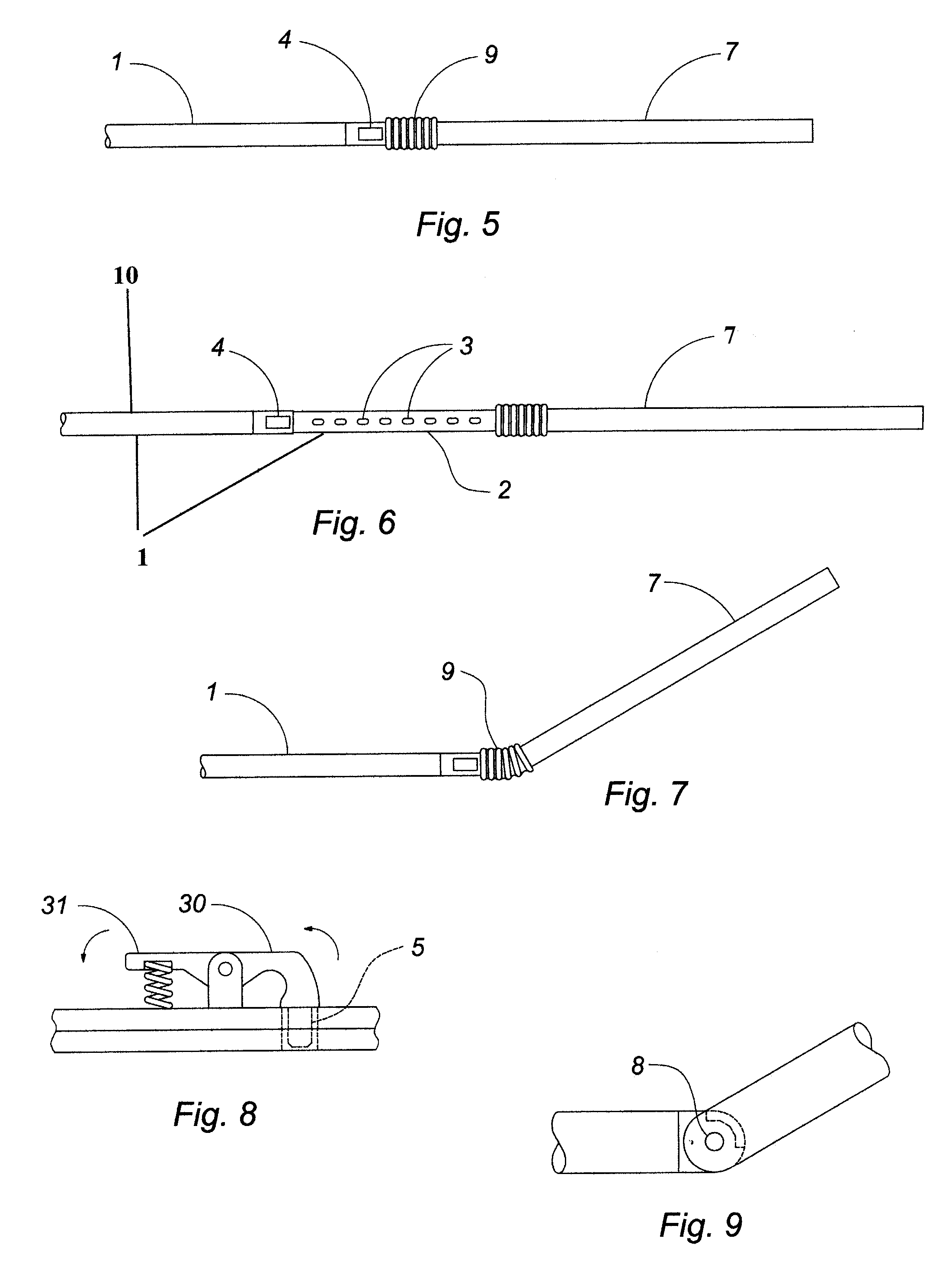
[0018]The present invention relates to a lotion applicator comprising an elongated shaft 1 formed of at least two length-adjustable sections. An inner section 2 having a plurality of longitudinal openings 3 is telescopically received within an outer section 10 having a spring-biased latch 4 at an end thereof. The latch includes a pivotal lever 30 with a pin 5 at a first end and a spring-biased button 31 at an opposing end. Depressing the button 31 lifts the pin 5 from a receiving aperture, allowing a user to adjust the length of the shaft, as desired.

[0019]Attached to the distal end of the outer section is an ovate applicator head 6 formed of a rigid inner shell 11 encapsulated by an outer layer 12 of silicone rubber. The head includes a relatively planar lower surface 15 and an arcuate upper surface 16, either of which can be used to apply lotion according to the contour of the target area. A handle 7 is pivotally connected to the distal end of the inner section with a spring-biase...


PUM


Abstract

A lotion applicator includes an elongated, telescoping shaft having an applicator head attached to an end thereof. Pivotally connected to an opposing end of the shaft is an angularly adjustable handle. Accordingly, a user places lotion on the applicator head and reciprocates it on a desired portion of the body. If necessary to reach a certain area, the shaft can be extended or retracted, and the handle can be adjusted to a desired angle.

Description

CROSS REFERENCE TO RELATED APPLICATIONS[0001]This application is entitled to the benefit of provisional patent application No. 61 / 763,114, filed on Feb. 11, 2013, the specification of which is incorporated herein by reference.BACKGROUND OF THE INVENTION[0002]The present invention relates to a tool for easily applying lotion to a desired body part.DESCRIPTION OF THE PRIOR ART[0003]Applying lotions to certain areas of the body can be difficult and challenging. Typically, the lotion is first delivered to the hands, which are then used to spread the lotion over other desired body parts. However, the elderly or those who are otherwise inflexible are unable to reach certain areas of the back or other remote areas without assistance. Conventional lotion applicators that purportedly overcome the aforementioned problems typically include an elongated handle having a sponge or brush at a distal end. However, because neither the handle nor the brush is adjustable, a user is often unable to eff...

Claims


Application Information

Patent Timeline
IPC IPC(8): A45D34/04A61M35/00A45D40/26
CPCA45D34/04A61M35/003A45D40/26A45D2200/1081
Inventor HUDSON, WILLIAM RUSSELL
Owner HUDSON WILLIAM RUSSELL
Why Eureka
Try Eureka