Scissor lift and use of a scissor lift

a scissor lift and scissor technology, applied in the direction of lifting frames, lifting devices, ambulance services, etc., can solve the problem of uneven power required to move the platform upwards

Inactive Publication Date: 2013-12-26
DEVELTEX APS
View PDF11 Cites 28 Cited by
  • Summary
  • Abstract
  • Description
  • Claims
  • Application Information

AI Technical Summary

Benefits of technology

[0026]Forming the legs with substantially equal length on both sides of the scissor joint is advantageous in that this provides for a symmetrically scissor mechanism design that will only lift the top frame vertically.
[0027]However in another embodiment the length of the part of the legs extending between the scissor joint and the bottom frame could be different and / or the length of the parts of the legs extending between the scissor joint and the top frame could be different, thus enabling that the scissor lift may also be used for tilting the top frame in relation to the bottom frame during a lifting process i.e. while the bottom ends of the legs are moved towards each other.

Problems solved by technology

However, the power required to move the platform upwards is very uneven over the full stroke of the platform in a traditional scissor lift design.

Method used


Image

  • Scissor lift and use of a scissor lift
  • Scissor lift and use of a scissor lift
  • Scissor lift and use of a scissor lift

Examples


Embodiment Construction

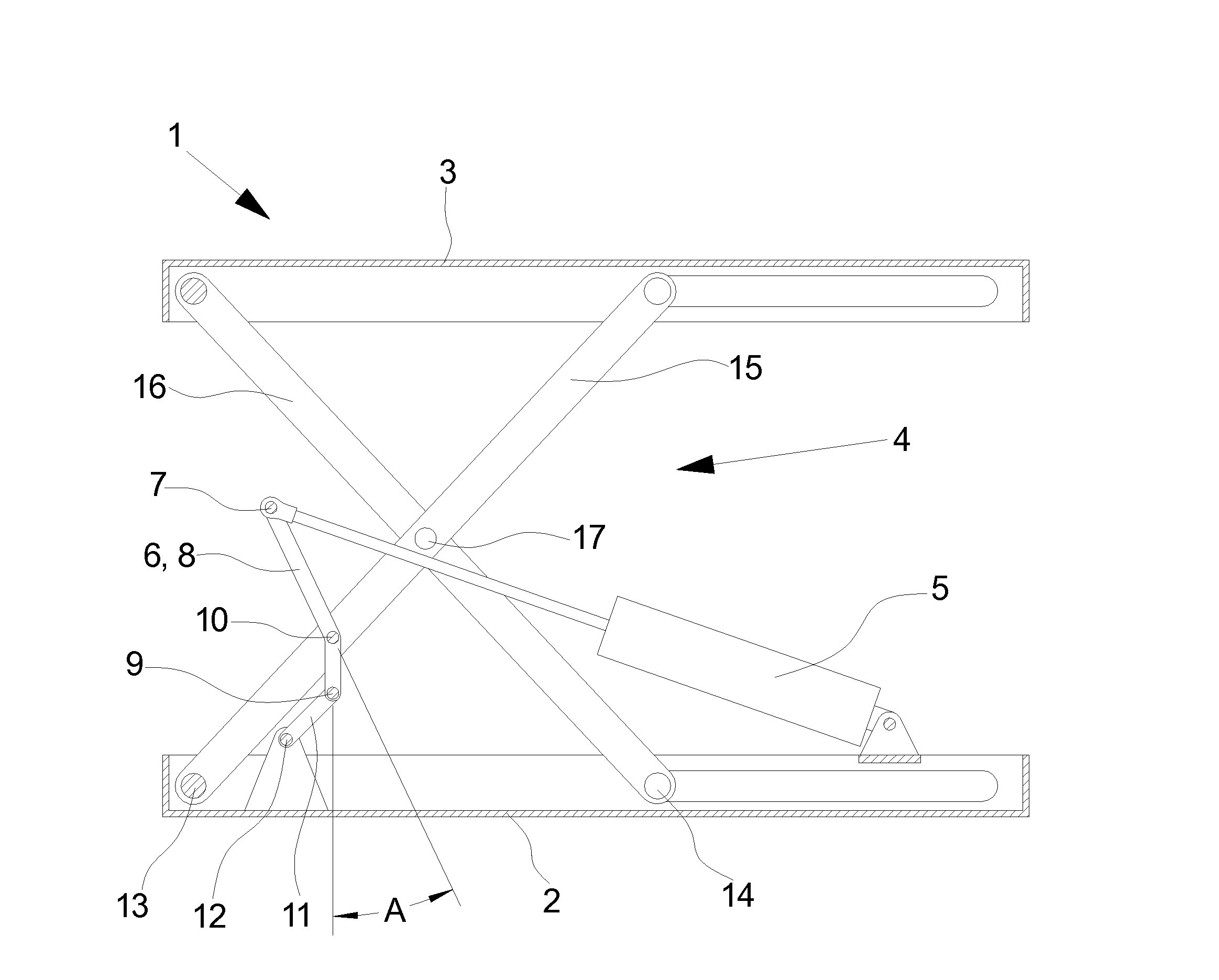
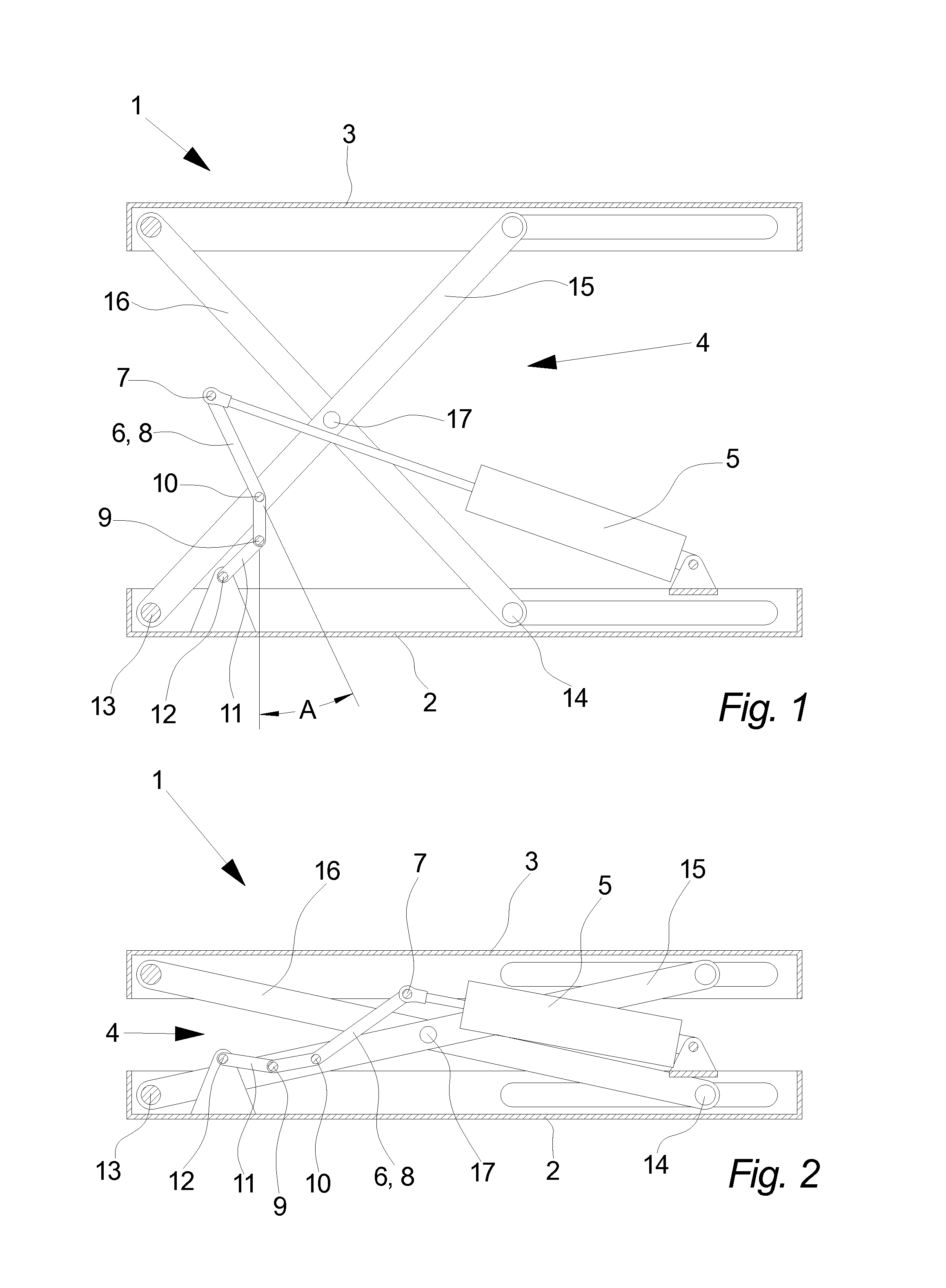
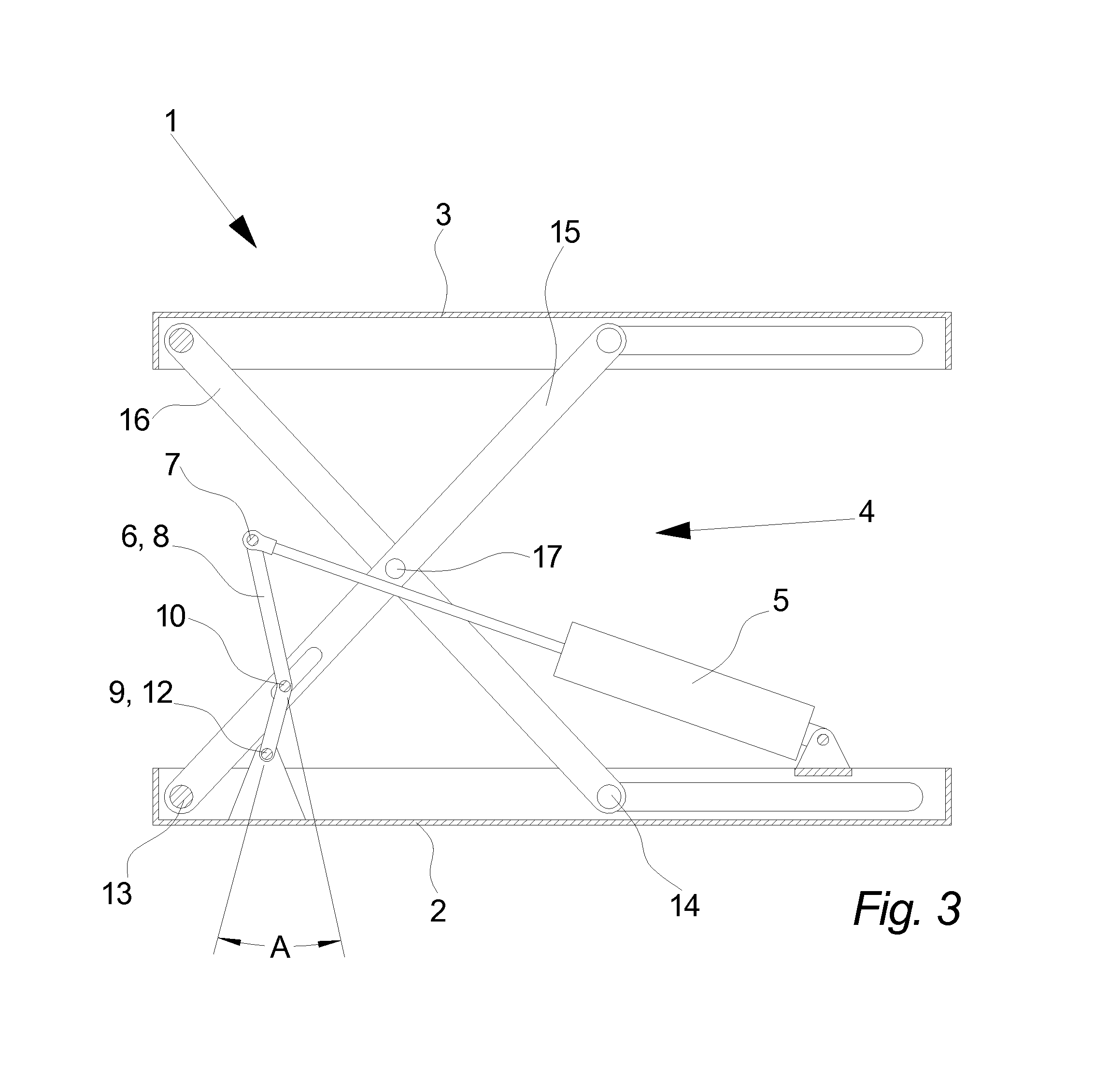
[0036]FIG. 1 illustrates a cross section through a scissor lift 1 according to the invention in an elevated state, as seen from the side.

[0037]In this embodiment of the invention the scissor mechanism 4 is constituted by two legs 15, 16 arranged in a X by means of the rotatable scissor joint 17 allowing the upper ends and the lower ends of the legs 15, 16 to move towards or away from each other. To ensure that the top frame 3—which in this embodiment is formed as a platform—is maintained substantially parallel with the bottom frame 2—which in this embodiment is formed as a sheet metal construction—the left end of the legs 15, 16 is connected to the bottom frame 2 and the top frame 3 respectively through fixed rotatable joints 13 and the right ends are connected to displaceable joints 14. The displaceable joints 14 allows the ends of the legs 15, 16 to travel controlled back and forth while being guided by track means of the frames 2, 3.

[0038]However, in another embodiment of the inv...


PUM


Abstract

Disclosed is a scissor lift including a bottom frame a top frame, a scissor mechanism arranged between the bottom frame and the top frame to displace the bottom frame and the top frame in relation to each other by means of the force provided by a linear actuator, a gearing arranged between the scissor mechanism and the linear actuator, where the linear actuator has a linear actuator point of attack at one end of a lever arm of the gearing, wherein the bottom frame is connected to a bottom frame point of attack at another end of the lever arm and wherein the scissor mechanism is connected to the lever arm through a lever arm pivotal joint arranged between the linear actuator point of attack and the bottom frame point of attack.

Description

FIELD OF THE INVENTION[0001]The invention relates to a scissor lift and use of a scissor lift.BACKGROUND OF THE INVENTION[0002]A scissor lift is a type of lift that can usually only move vertically. The mechanism to achieve this is the use of linked, folding supports in a single or criss-cross “X” pattern, known as a scissor mechanism or pantograph. The upward motion is achieved by the application of pressure to the lowest set of supports, elongating the crossing pattern, and propelling a platform vertically.[0003]The extension and contraction of the scissor action can e.g. be hydraulic, pneumatic or mechanical (via a leadscrew or rack and pinion system). In hydraulic and pneumatic systems, it may require no power to enter “descent” mode, but rather a simple release of hydraulic or pneumatic pressure. This is the main reason that these methods of powering the lifts are preferred, as it allows a fail-safe option of returning the platform to a contracted state by release of a manual v...

Claims


Application Information

Patent Timeline
Patent Type & Authority Applications(United States)
IPC IPC(8): B66F7/06A61G5/10
CPCB66F7/065A61G5/1059B66F7/0608
Inventor OLESEN, MARTIN
Owner DEVELTEX APS
Why Eureka
Try Eureka