Vibration-powered generator

a generator and vibration technology, applied in the direction of dynamo-electric machines, electrical apparatus, etc., can solve the problems of magnet fracture, easy breakage of the proportion between the magnetic rod and the magnet, etc., and achieve excellent mechanical strength and durability

Active Publication Date: 2013-12-26
SUMIDA CORP
View PDF3 Cites 8 Cited by
  • Summary
  • Abstract
  • Description
  • Claims
  • Application Information

AI Technical Summary

Benefits of technology

[0010]According to the present invention, there is provided a vibration

Problems solved by technology

The vibration-powered generator disclosed in Patent Document 1, however, suffers from a problem that a portion connecting the magnetic rod and the magnets may readily be broken when the vibrating element is applied with an impact force at both ends of the reciprocating vibration, since the magnets are connected only with a thin ma

Method used


Image

  • Vibration-powered generator
  • Vibration-powered generator
  • Vibration-powered generator

Examples


Embodiment Construction

[0019]Embodiment of the present invention will be explained referring to the attached drawings. Note that all similar constituents in all drawings will be given similar reference numerals, so as to appropriately avoid repetitive explanations.

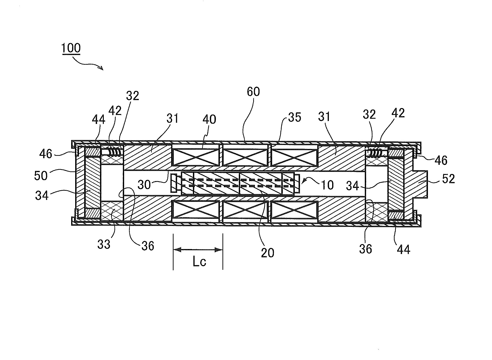
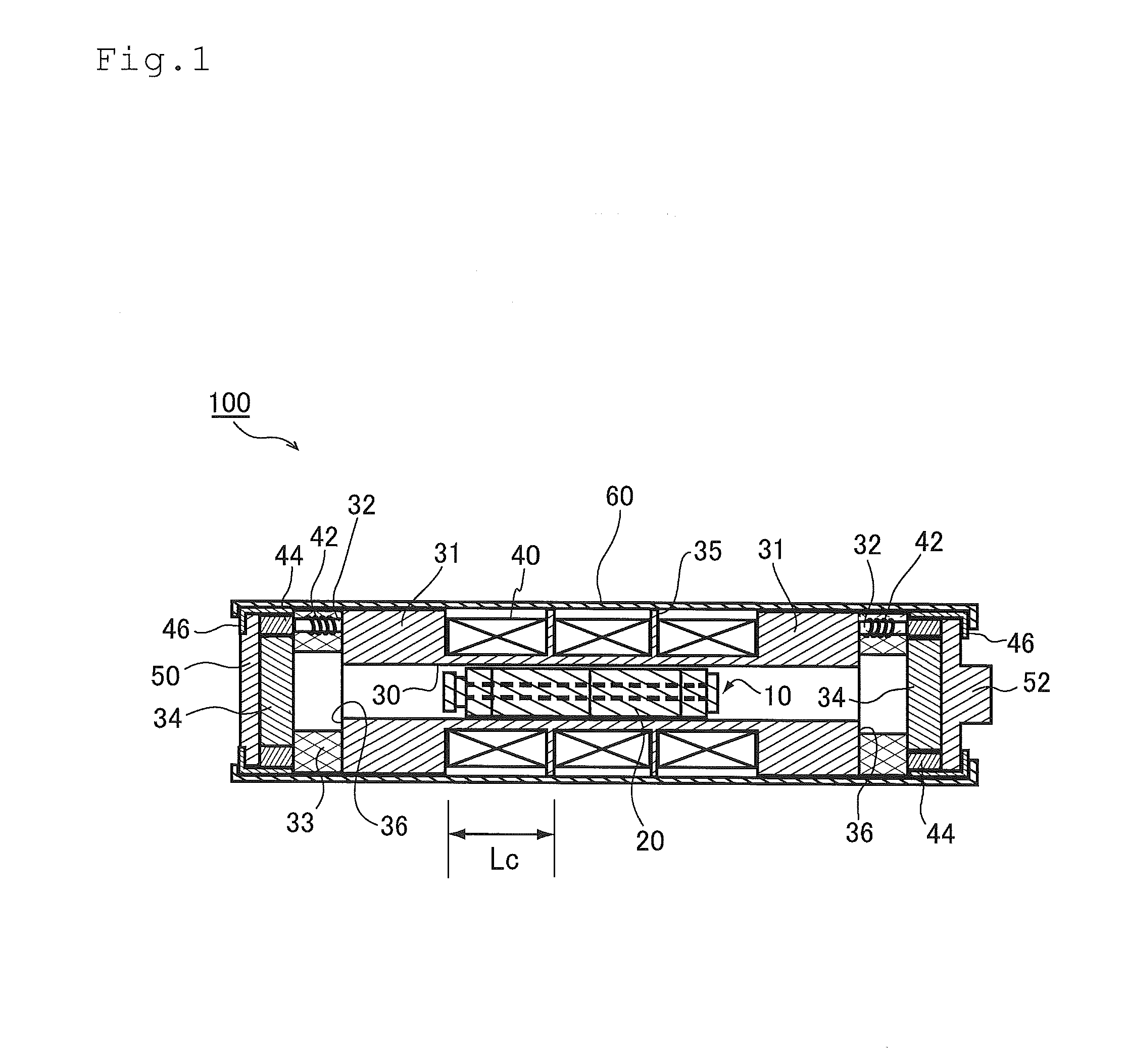
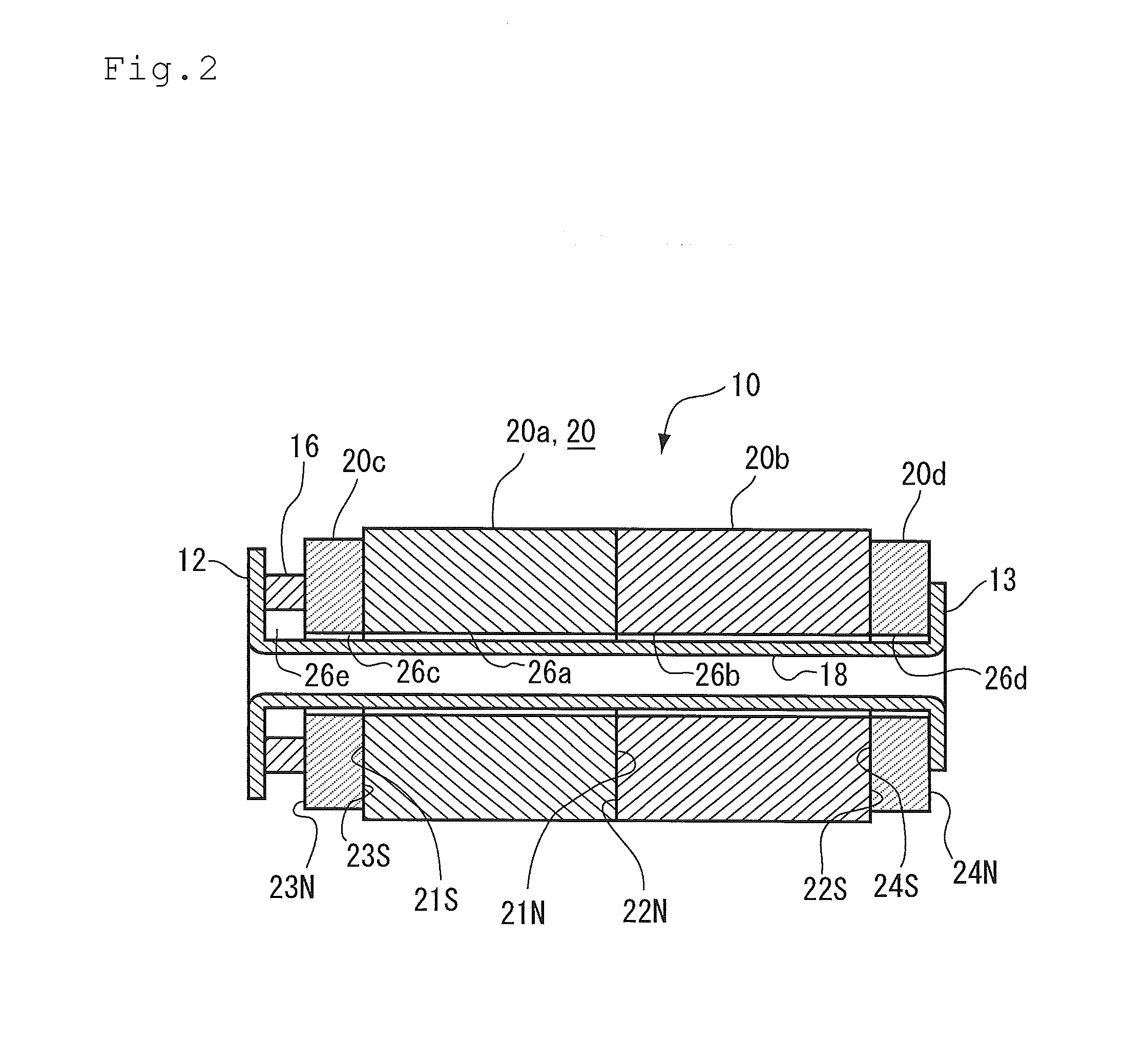
[0020]FIG. 1 is a longitudinal cross sectional view of a vibration-powered generator 100 according to one embodiment of the present invention, taken along the axis of vibration. The direction of the axis of vibration lies in agreement with the lateral direction of FIG. 1. FIG. 2 is a drawing of a vibrating element 10, taken along the axis of vibration thereof.

[0021]First, the vibration-powered generator 100 of this embodiment will be outlined.

[0022]The vibration-powered generator 100 has the vibrating element 10 which includes a plurality of magnets 20 (20a to 20d), end supporting portions 12, 13 and a cushioning 16, and coils 40 arranged around the vibrating element 10, and is configured to obtain electromotive force by moving the vibrating ele...


PUM


Abstract

A vibration-powered generator (100) has a vibrating element (10) and a coil (40) arranged therearound, and is configured to obtain electromotive force by moving the vibrating element (10) relatively to the coil (40). The vibrating element (10) has a plurality of magnets (20a to 20d) arranged so as to oppose the pole-faces of the same polarity; end supporting portions (12, 13) which support the plurality of magnets from both ends in the direction of arrangement; and a cushioning (16). The cushioning (16) is held between the end supporting portion (12) and the magnet (20c), while being compressed under a stress exceeding the repelling force between the pole-faces of the magnets, so as to keep the magnets (20a to 20d) in a row without leaving a gap in between, overcoming the repelling force.

Description

TECHNICAL FIELD[0001]The present invention relates to a vibration-powered generator configured to obtain electromotive force by moving a vibrating element with a built-in magnet relatively to a coil.BACKGROUND ART[0002]There has been a demand on simple power generators, capable of compensating or substituting disposal dry cells, from the viewpoints of sustaining or improving the global environment, and of ensuring emergency power supply. Of these sorts of power generators, there has been proposed a vibration-powered generator configured to generate induced current by allowing a permanent magnet to vibrate in a reciprocating manner inside a coil. Regarding this sort of technology, Patent Document 1 discloses a vibration-powered generator configured to allow a vibrating element, having two magnets arranged so as to oppose the pole-faces of the same polarity while keeping a gap in between, to vibrate in a reciprocating manner relative to a coil. The two magnets are connected to each ot...

Claims


Application Information

Patent Timeline
IPC IPC(8): H02K35/02
CPCH02K35/02
Inventor KAWARAI, MITSUGUYAMAGUCHI, TAKAYUKIILJIMA, RYUTATAKAHASHI, RYOYANISHIHARA, KEISUKE
Owner SUMIDA CORP
Why Eureka
Try Eureka