
Hybrid force sensitive touch devices

a touch device and hybrid force technology, applied in the direction of instruments, computing, electric digital data processing, etc., can solve the problems of inability to differentiate two or more touches, logic failure, and difficulty in producing high-quality touch screen solutions

Active Publication Date: 2013-12-26
APPLE INC
View PDF26 Cites 90 Cited by
  • Summary
  • Abstract
  • Description
  • Claims
  • Application Information

AI Technical Summary

Benefits of technology

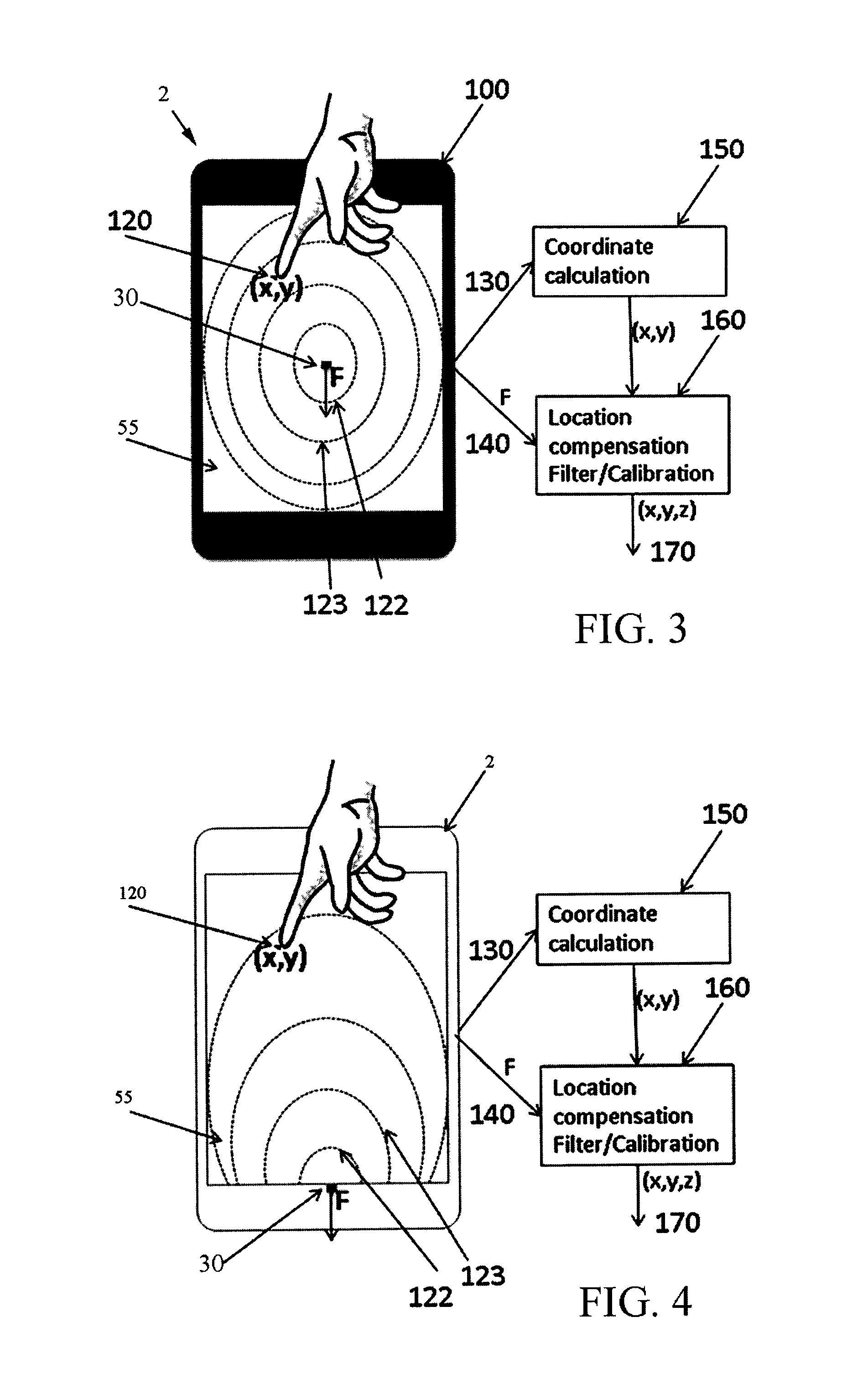
The present invention relates to touch sensor controls with both touch coordinate and force sensing ability. The technical effect of this invention is to provide a high quality touch screen solution with a touch screen technology that can measure both touch coordinates and the absolute amount of touch force. This is important because existing touch screen technologies come with a unique set of advantages and disadvantages, and so it is difficult to find one that completely replaces another. The invention combines the advantages of multiple touch screen technologies to create a touch screen solution with the highest quality touch screen capabilities.

Problems solved by technology

The concept of using multiple force sensing sensors to register, measure and triangulate the touched position of a touch screen has been a known concept for more than twenty years, however, to produce a high quality touch screen solution has proven difficult.
Over the last few years the performance trade-offs of the available force sensing technologies has fragmented the market.
However, only one such technology has been adapted to measure both the touch coordinates as well as the absolute amount of touch force.
Unfortunately, this logic fails if the user is using a finger nail or a stylus.
For example, force-based touch screen technology is only capable of discerning a single touch, and cannot differentiate two or more touches (“multi-touch”).
Indeed, all existing touch screen technologies come with a unique set of advantages and disadvantages, and so it is unlikely that any one will completely replace any other.
This technology supports multi-touch and will react to extremely light touches, however, it cannot measure force, nor can it recognize a touch from objects other than fingers or specialized styluses.

Method used


Image

  • Hybrid force sensitive touch devices
  • Hybrid force sensitive touch devices
  • Hybrid force sensitive touch devices

Examples


Embodiment Construction

[0018]The present invention is a hybrid touch-screen display that integrates force-based touch-screen technology with any one from among a group of projective capacitive, surface capacitive, resistive, digital resistive, SAW, IR, APR, DST, optical and electromagnetic touch-screen technologies.

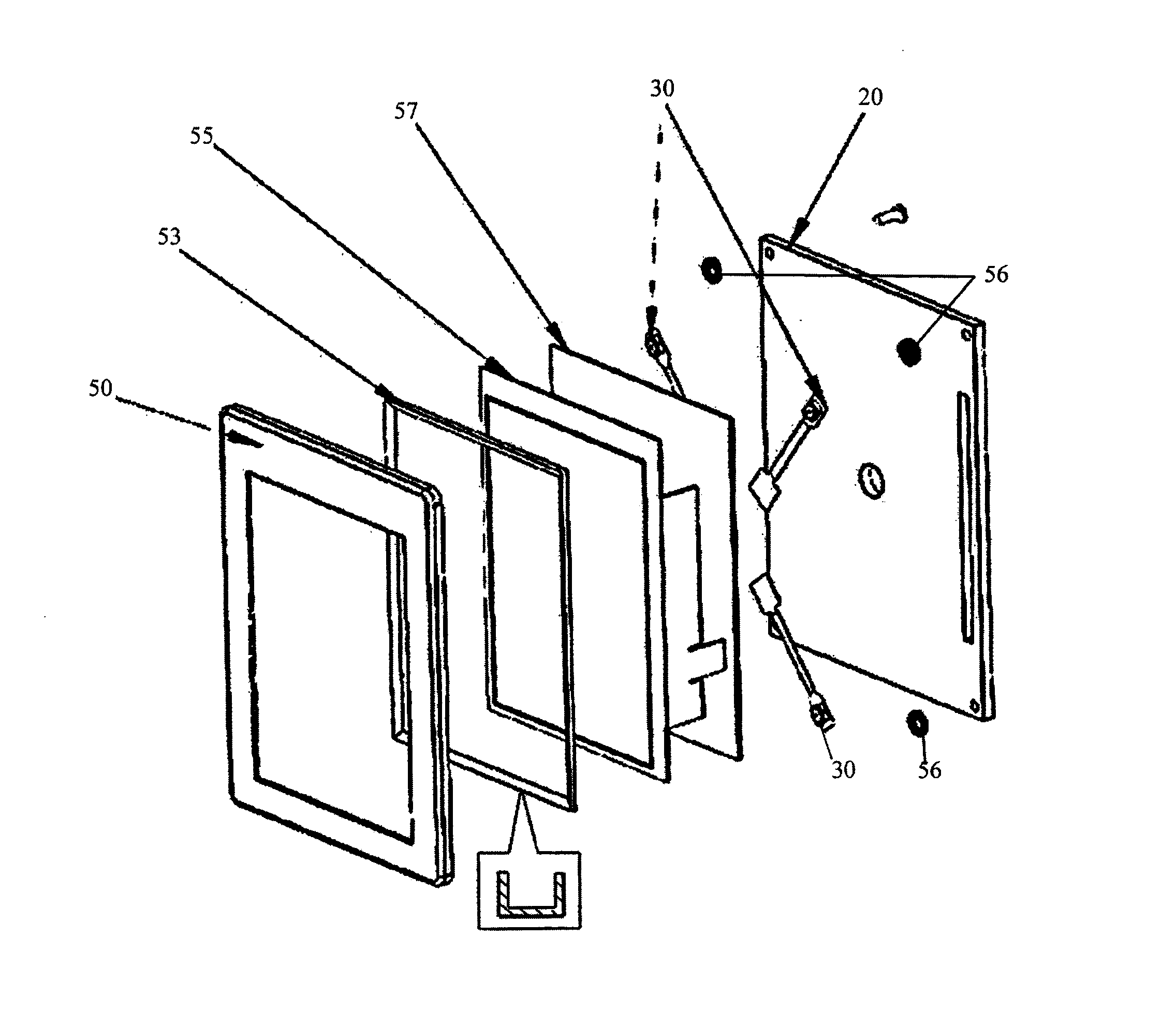
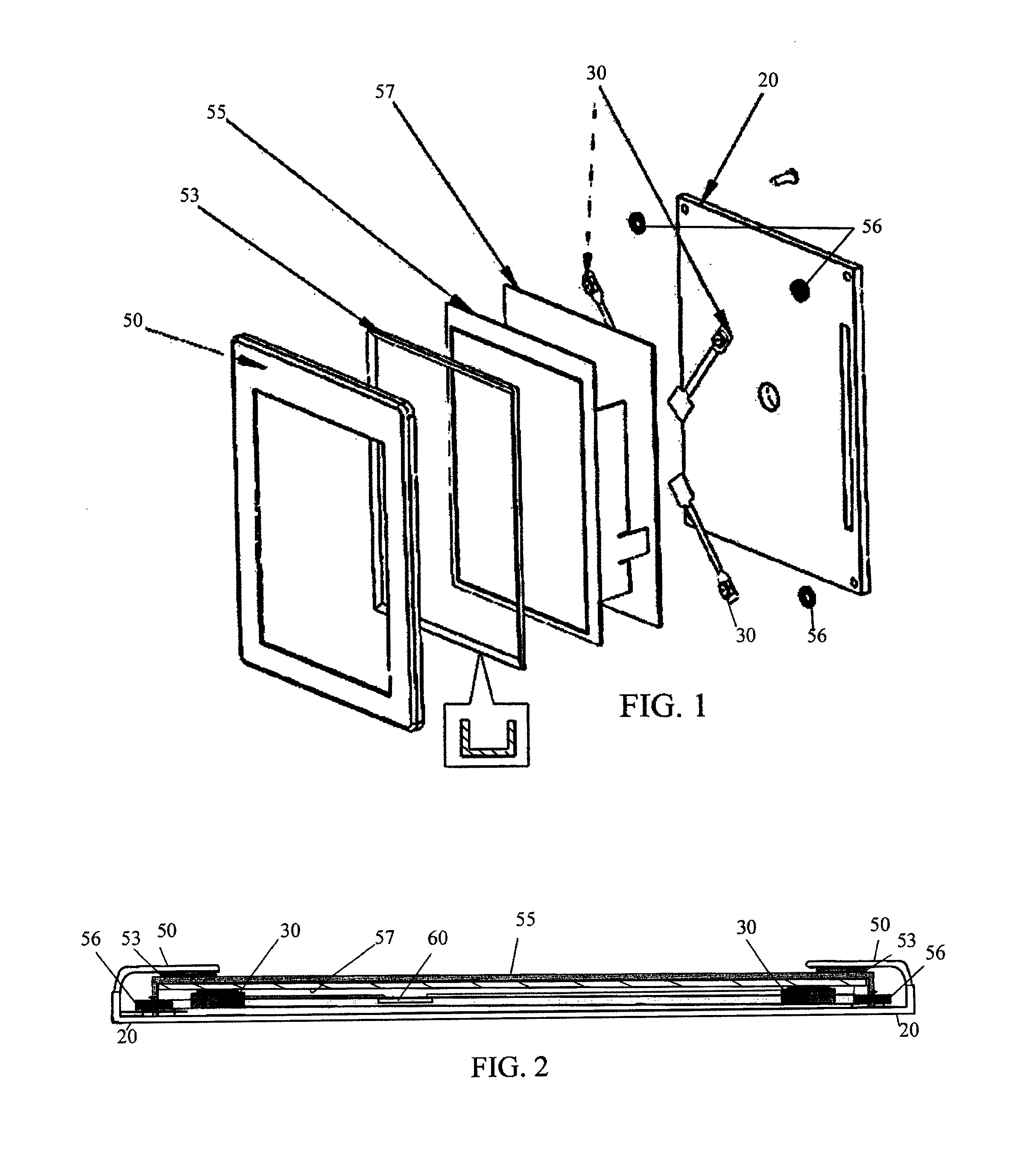
[0019]FIG. 1 is an exploded perspective view of a hybrid touch-screen display employing the foregoing principles, and FIG. 2 is a side cross-section of the touch screen system of FIG. 1. With collective reference to FIGS. 1-2, the illustrated embodiment employs a Projective Capacitive (ProCap) touch display screen 55, a support structure 57 for the display screen 55, and one or more force sensors 30 (here four corner-mounted force sensors 30 shown). The force sensor(s) 30 may be affixed directly (surface-mounted) to the back of the support structure 57 or indirectly (by traces as shown) to a sensor printed circuit board (not shown) which is in turn attached to an opposing base substrate 20 (whi...


PUM


Abstract

A hybrid touch-screen display that integrates force-based touch-screen technology with any one from among a group of projective capacitive, surface capacitive, resistive, digital resistive, SAW, IR, APR, DST, optical and electromagnetic touch-screen technologies to provide an ability to compensate for non-perfect force transfer. An alternate implementation is also disclosed that employs a single force sensor for relative force measurement in a system in which force is traditionally not measured, here a water dispenser unit. This allows compensation for varying static loads, run-time calibration, and filtering of extraneous loads through firmware.

Description

CROSS-REFERENCE TO RELATED APPLICATION(S)[0001]The present application claims priority based on U.S. Provisional Patent Application 61 / 658,020 filed Jun. 11, 2012. And is a continuation-in-part of U.S. patent application Ser. No. 13 / 425,846 filed 21 Mar. 2012, which is a continuation-in-part of U.S. patent application Ser. No. 12 / 450,138; filed 11 Sep. 2009, which is a national phase entry of International Application PCT / US2008 / 003374, which in turn claims priority based on U.S. Provisional Patent Application 60 / 918,275 filed 15 Mar. 2007.BACKGROUND OF THE INVENTION[0002](1) Field of the Invention[0003]The present invention relates to touch sensor controls including touch input systems (touch screens used in fixed or mobile devices, such as point of sales terminals, kiosks, laptops, monitors, POS, POI, PDAs, cell phones, UMPCs and the like). More particularly, the invention relates to touch sensor controls having both a touch-coordinate calculation ability as well as a force sensin...

Claims


Application Information

Patent Timeline
IPC IPC(8): G06F3/041
CPCG06F3/0416G06F3/04142G06F3/04186G06F3/042G06F3/043G06F3/044G06F3/045G06F3/046G06F2203/04105G06F2203/04106
Inventor MOLNE, ANDERS L.GRIFFITH, DAVID
Owner APPLE INC
Learn More