Pressure-sensitive touch panel

A panel, capacitive touch technology, applied in the direction of instrument, electrical digital data processing, data processing input/output process, etc., can solve the problems of complex production cost, high cost, huge touch panel and other problems of the system

Active Publication Date: 2018-08-28
CAMBRIDGE TOUCH TECH
View PDF14 Cites 5 Cited by
  • Summary
  • Abstract
  • Description
  • Claims
  • Application Information

AI Technical Summary

Problems solved by technology

However, systems that use separate electrodes and/or separate electronics to sense changes in capacitance and/or changes in pressure can make the touch pane

Method used


Image

  • Pressure-sensitive touch panel
  • Pressure-sensitive touch panel
  • Pressure-sensitive touch panel

Examples


Embodiment Construction

[0072] In the following description, similar components are designated by similar reference numerals.

[0073] Self-capacitance and pressure combined measurement

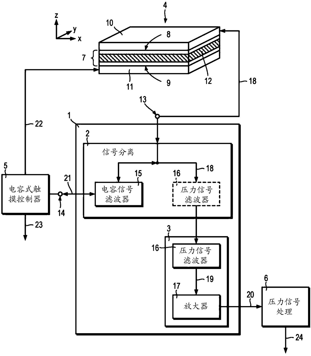
[0074] figure 1 A device 1 and a touch sensor 4 for combined capacitive and pressure measurements are shown.

[0075] see figure 1 , the device 1 for combined measurement of capacitance and pressure includes a signal separation stage 2 and an amplification stage 3 . The device 1 is connected to a touch sensor 4 , a capacitive touch controller 5 and a pressure signal processing module 6 . The device 1 enables capacitive and pressure measurements by the touch sensor 4 simultaneously using a pair of electrodes.

[0076] The first touch sensor 4 includes a layer structure 7 , a first sensing electrode 10 and a common electrode 11 , the layer structure 7 has a first surface 8 and a second surface 9 opposite to each other. The layer structure 7 comprises one or more layers comprising at least a layer 12 of piezoele...


PUM


Abstract

A device (48) for combined capacitance and pressure measurements includes a plurality of first input/output terminals (13) for a projected capacitance touch panel (36, 53, 58, 80), the touch panel (36, 53, 58, 80) including a layer of piezoelectric material (12) disposed between a plurality of sensing electrodes (10, 31) and a common electrode (11). The device (48) includes a plurality of second input/output terminals (14) for a capacitive touch controller (5). The device (48) includes a plurality of separation stages (2, 70, 76), each separation stage (2, 70, 76) connecting one first input/output terminal (13) to a corresponding second input/output terminal (14), and including a first frequency-dependent filter (15; Fig.1) for filtering signals (21, 33, 34) between respective first and second input/output terminals (13, 14). The device (48) includes at least one amplification stage (3, 71, 77), each amplification stage input is connected to one or more of the first input/output terminals (13) through the respective separation stage(s) (2, 70, 76). Each amplification stage (3, 71, 77) or each separation stage (2, 70, 76) includes a second frequency-dependent filter (16; Fig. 1) forfiltering signals between the respective first input/output terminal (13) and an amplification stage input. Each first frequency-dependent filter (16; Fig.1) is configured to pass signals (21, 33, 34) from the capacitive touch controller (5) and each second frequency-dependent filter (16; Fig.1 ) is configured to attenuate signals (21, 33, 34) from the capacitive touch controller (5).

Description

technical field [0001] The invention relates to a touch panel for combined capacitive and pressure sensing. Background technique [0002] Resistive touch panels and capacitive touch panels are used as input devices for computers and mobile devices. One class of capacitive touch panels, projected capacitive touch panels, is often used in mobile devices because the outer layers can be made of glass that provides a scratch-resistant hard surface. An example of a projected capacitive touch panel is described in US 2010 / 0079384 A1. [0003] Projected capacitive touch panels work by detecting changes in electric fields caused by the proximity of conductive objects. An array or grid of capacitive sensors is often used to determine where a projected capacitive touch panel is touched. While projected capacitive touch panels can generally distinguish between single and multiple touch events, they suffer from the inability to sense pressure. As a result, projected capacitive touch ...

Claims


Application Information

Patent Timeline
IPC IPC(8): G06F3/041G06F3/044
CPCG06F3/0412G06F2203/04105G06F2203/04106G06F2203/04107G06F3/0446G06F3/04144G06F3/04182G06F3/0445G06F3/044G06F3/0418G06F3/045G06F2203/04108
Inventor 西蒙·班克斯阿罗基亚·内森
Owner CAMBRIDGE TOUCH TECH
Why Eureka
Try Eureka