Ethernet chain protection switching

a technology of ethernet chain protection and switching, applied in the field of data communication networks, can solve the problems of low network protection, high cost, switching time,

Active Publication Date: 2013-12-26
TEJAS NETWORKS
View PDF11 Cites 27 Cited by
  • Summary
  • Abstract
  • Description
  • Claims
  • Application Information

AI Technical Summary

Benefits of technology

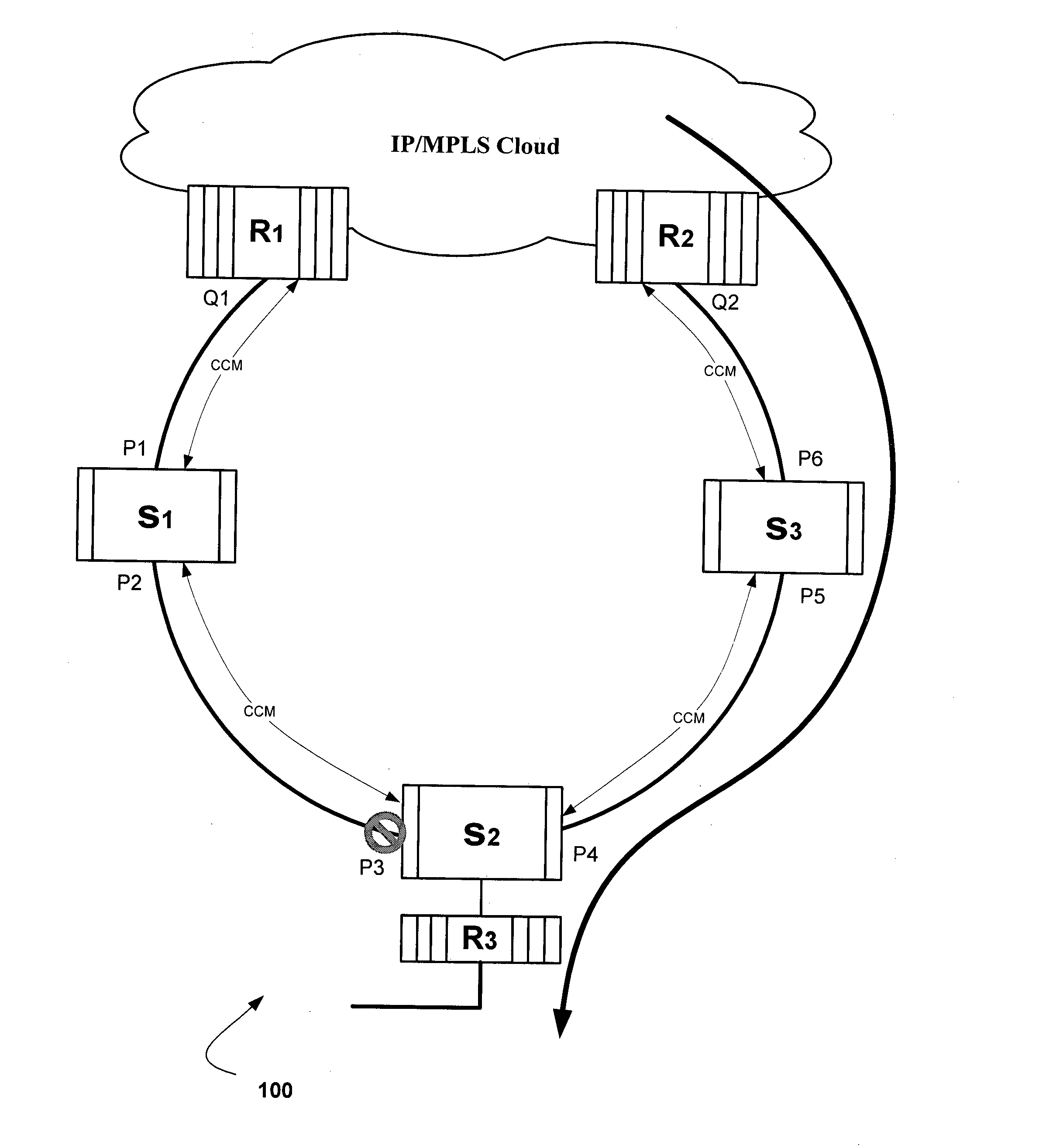
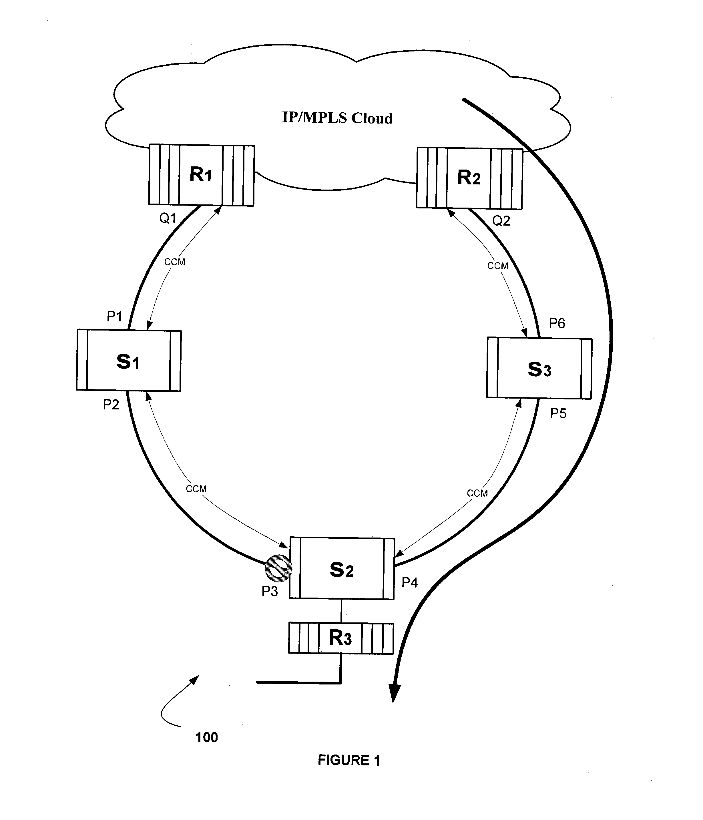
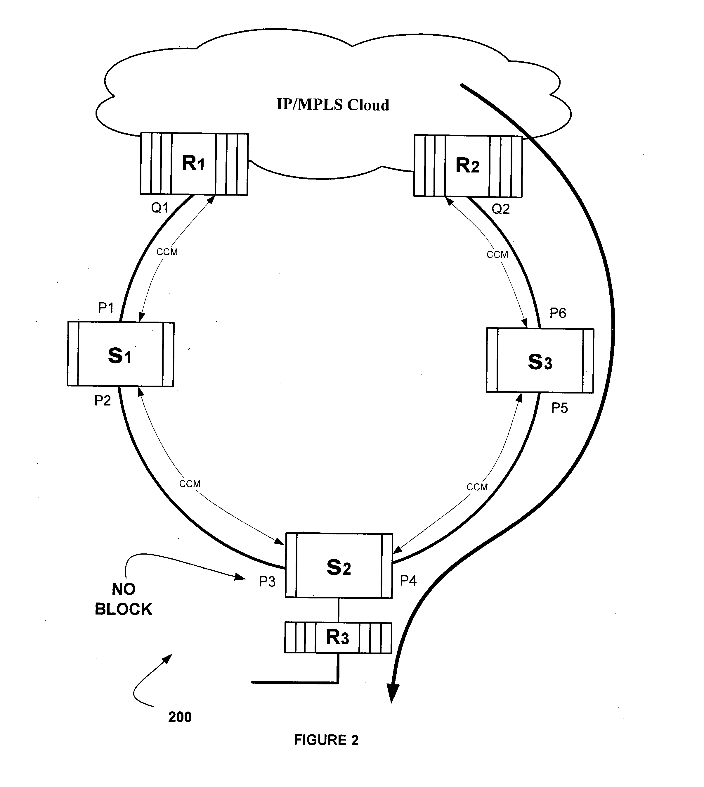
[0011]In yet another aspect of the present invention provide a protection switching system in a communication network, the communication network including plurality of communication device and at least one non-ERPS (Ethernet Ring Protection Switching) device connecting at least two terminal ports of the linear chain and thereby forming a ring, the system comprising: a plurality of communication devices interconnected in a ring topology, at least one non-ERPS device within the network; and a network channel connected to each of the communication device for transmitting and receiving Continuity Check Message (CCMs) or other types of message exchanges signifying channel being fault-less, where...

Problems solved by technology

For example, Ethernet-based access and aggregation networks are typically designed in a tree structure, and thus lack network protection and has only restoration mechanism.
To increase the bandwidth with the Ethernet-over-SONET and Ethernet-over-SDH leads to higher cost.
The major problems with this type of path protection scheme are: (1) switching time in response to a fault is relatively slow, (2) cannot offer QoS because of in-deterministic tree; and (3) comple...

Method used


Image

  • Ethernet chain protection switching
  • Ethernet chain protection switching
  • Ethernet chain protection switching

Examples


Embodiment Construction

[0023]The following description with reference to the accompanying drawings is provided to assist in a comprehensive understanding of exemplary embodiments of the invention as defined by the claims and their equivalents. It includes various specific details to assist in that understanding but these are to be regarded as merely exemplary. Accordingly, those of ordinary skill in the art will recognize that various changes and modifications of the embodiments described herein can be made without departing from the scope and spirit of the invention. In addition, descriptions of well-known functions and constructions are omitted for clarity and conciseness.

[0024]The terms and words used in the following description and claims are not limited to the bibliographical meanings, but, are merely used by the inventor to enable a clear and consistent understanding of the invention. Accordingly, it should be apparent to those skilled in the art that the following description of exemplary embodime...


PUM


Abstract

The present invention relates to a protection switching method in a communication network, the communication network including plurality of communication devices forming a linear chain and at least one non-ERPS on the nodes ERPS (Ethernet Ring Protection Switching) device connecting terminal ports of the linear chain and thereby forming a ring. In one embodiment this is accomplished by instantiating ERPS on each communication device that forms a linear chain and on each non-terminal ports of the linear chain, identifying a node or link fault in the network, wherein the link or node fault is detected by Continuity Check Message (CCM), Loss of Light (LOL), Loss of Signal (LOS), Loss of periodic continuity check messages (IEEE 802.1 ag) or any other mechanisms thereof, blocking ports of the communication device in response to the detection of fault, periodically broadcasting a fault message by the blocked ports of the communication devices, wherein the message gets terminated at the ports of the communication device within the linear chain network without reaching the non-ERPS device, flushing the Media Access Control (MAC) table entry upon receipt of the fault message by all the communication device and unblocking of a root port link (RPL) of the linear for providing an alternate path to route network traffic after receipt of the fault message.

Description

FIELD OF THE INVENTION[0001]The present invention is directed to the field of data communication networks. More particularly, the present invention provides a protection switching method and system of a node having communication failure in a ring, in a communication network.BACKGROUND OF THE INVENTION[0002]Communication networks can be built in many different network topologies, such as a ring, mesh, linear, linear chain, tree, and the like. Conventionally, network protection is provided for at layers one and below, such as through SONET, SDH, and the like. Typical protection schemes can include Automatic Protection Switching (APS), Uni-directional Path Switched Rings (UPSRs), two and four fiber Bi-directional Line Switched Rings (BLSRs), and the like. Traditionally, networks are typically not protected using ring protection schemes at layer two (e.g., Ethernet) and above. For example, Ethernet-based access and aggregation networks are typically designed in a tree structure, and thu...

Claims


Application Information

Patent Timeline
IPC IPC(8): H04L12/24H04L45/02
CPCH04L41/0654H04L12/437H04L45/02
Inventor MADAIAH, VINOD KUMAROJHA, SOMNATHARAVINDAKSHAN, JISHNUKIRSHNAMOOTHY, BALASUBRAMANIAN
Owner TEJAS NETWORKS
Why Eureka
Try Eureka