Control device, control method, and control program for articulated robot

a robot and control device technology, applied in the direction of program control, electric programme control, instruments, etc., can solve the problem that the angle of the j5 axis cannot be made to reach the angle to be taken at the work end poin

Active Publication Date: 2013-12-26
KOBE STEEL LTD
View PDF8 Cites 21 Cited by
  • Summary
  • Abstract
  • Description
  • Claims
  • Application Information

AI Technical Summary

Benefits of technology

[0021]According to the present invention, the respective angles of the drive shafts of the first articulated drive system can be made to reliably reach the angles to be taken at the work end point while the position and the moving speed of the working part at the...

Problems solved by technology

In that case, however, when the angle of the J5 axis takes different sings at the work start point and t...

Method used


Image

  • Control device, control method, and control program for articulated robot
  • Control device, control method, and control program for articulated robot
  • Control device, control method, and control program for articulated robot

Examples


example 1

[0087]In EXAMPLE 1, another example of the exception example in the above-described robot control process (see FIG. 3) is described.

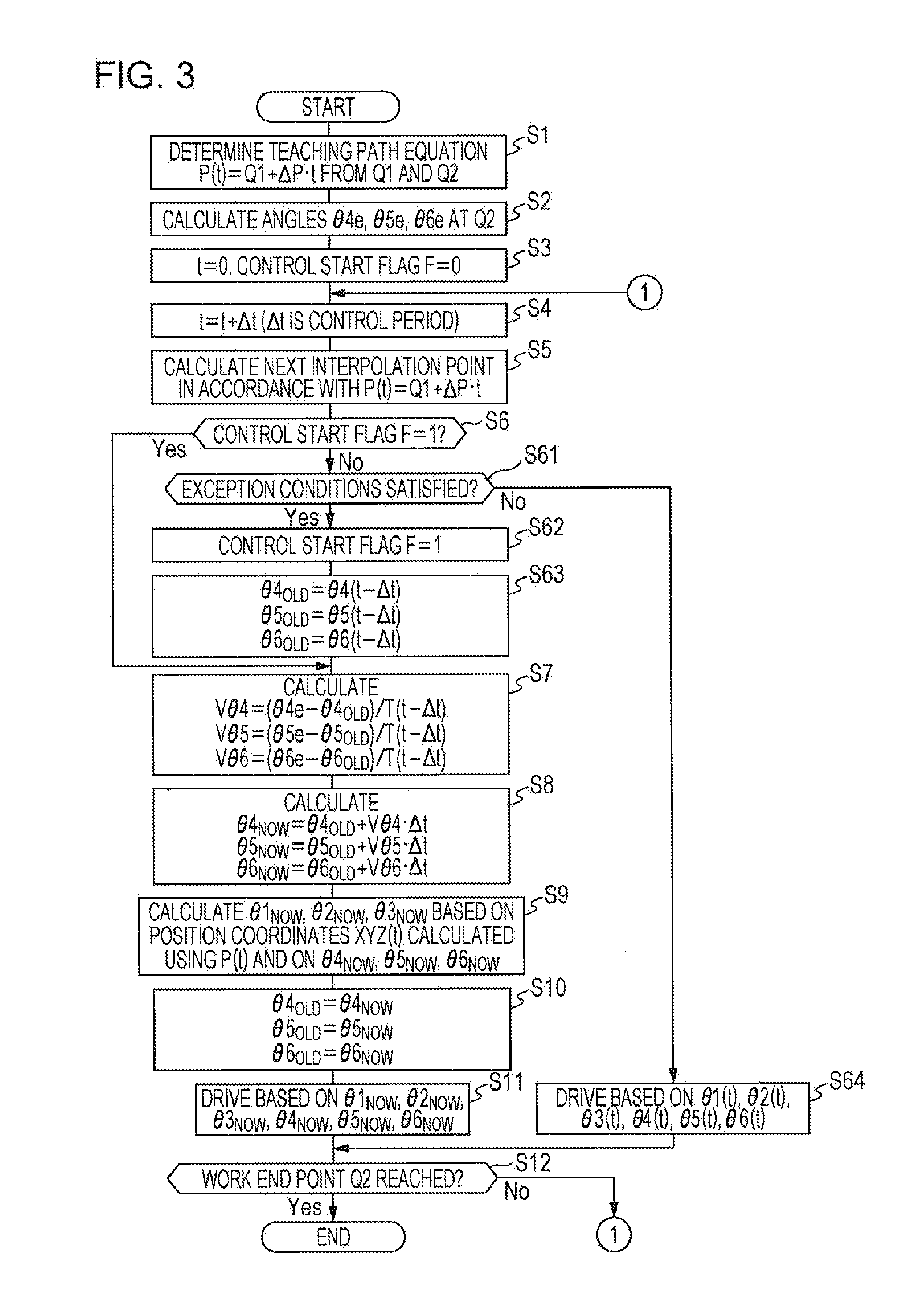
[0088]More specifically, in EXAMPLE 1, the control device 1 determines in above step S61 that the exception condition is satisfied, when the angle of at least one of the drive shafts 34 to 36 at the next interpolation point exceeds a preset operation range. Assuming, for example, that respective limits of preset plus-side operation ranges of the drive shafts 34 to 36 are θ4+L, θ5+L and θ6+L, and that respective limits of preset minus-side operation ranges of the drive shafts 34 to 36 are θ4−L, θ5−L and θ6−L, the control device 1 determines that the exception condition is satisfied, when at least one of the following formulae (41) to (46) is held. The operation ranges of the drive shafts 34 to 36 are, for example, allowable operation ranges of drive motors for the drive shafts 34 to 36.

θ4(t)>θ4+L  (41)

θ4(t)<θ4−L  (42)

θ5(t)>θ5+L  (43)

θ5(t)5−L  (44)

θ6(t)>θ...

example 2

[0095]Another example of the above-described exception condition used in the robot control process (see FIG. 3) will be described in EXAMPLE 2.

[0096]FIG. 9 is a flowchart illustrating one example of procedures of a robot control process according to EXAMPLE 2. It is to be noted that similar processing procedures to those in the above-described robot control process (see FIG. 3) are denoted by similar symbols and description thereof is omitted.

[0097]More specifically, as illustrated in FIG. 9, steps S21, S31, S41 and S611 described below are executed in the robot control process according to EXAMPLE 2 instead of above steps S2, S3, S4 and S61, respectively.

(Steps S21, S31 and S41)

[0098]In step S21, the control device 1 calculates not only the angles θ4e, θ5e and θ6e of the drive shafts 34 to 36 at the work end point Q2, but also the angles θ4s, θ5s and θ6s of the drive shafts 34 to 36 at the work start point Q1.

[0099]In step S21, the control device 1 further calculates respective ang...

example 3

[0108]EXAMPLE 3 is intended to execute copying control in which the control device 1 controls the articulated robot 3 in such a manner that the end effector 2 is moved to trace a work line of a workpiece. In this case, a sensor (corresponding to deviation amount detecting means) for detecting a deviation amount ΔXYZαβγ(t) between the end effector 2 and the work line is disposed on the articulated robot 3.

[0109]Herein, the deviation amount ΔXYZαβγ(t) detected by the sensor at each detection time is a value represented on the basis of the interpolation point at the relevant detection time, which is calculated using the above-described path equation P(t). The control device 1 executes the copying control for moving the end effector 2 to trace the work line based on the detection result of the sensor. The control device 1 in executing the copying control corresponds to copying control means.

[0110]In more detail, when calculating the next interpolation point in step S5 of the above-descr...


PUM

PropertyMeasurementUnit
Angleaaaaaaaaaa
Speedaaaaaaaaaa
Distanceaaaaaaaaaa

Abstract

The purpose of the present invention is to have the angles of each of the drive shafts of the first articulated drive system infallibly reach the angle of the work completed position, while maintaining the rate of movement and position of the working parts of an articulated robot. If exception conditions are not satisfied, the drive shafts of first and second articulation drive systems are driven individually (S64) on the basis of interpolated points calculated in step 5 (S5). After exception conditions are satisfied (Yes side of S61), until the working parts reach the work completed position (No side of S12), the angle of each of the drive shafts of the first articulated drive system required to vary each of the drive shafts of the first articulated drive system in a linear manner with the angle at the work completed position as a target is calculated (S8), and the angle of each of the drive shafts of the second articulated drive system is calculated on the basis of the position of the working part at the interpolated point calculated in step 5 (S5) and the angle of each of the drive shafts of the first articulated drive system as calculated (S9), and the drive shafts of the first and second articulated drive systems are driven according to said calculation results (S11).

Description

TECHNICAL FIELD[0001]The present invention relates to a control technique for an articulated robot including a first articulated drive system, which includes three drive shafts for changing an attitude of a working part disposed at a forward end, and a second articulated drive system, which includes at least three drive shafts for changing a position of the first articulated drive system.BACKGROUND ART[0002]A 6-axis manipulator, illustrated in FIG. 23, as one type of an articulated robot includes a first articulated drive system, which includes a J4 axis, a J5 axis, and a J6 axis for changing an attitude of an end effector (working part) disposed at a forward end, and a second articulated drive system, which includes a J1 axis, a J2 axis, and a J5 axis for changing a position of the first articulated drive system. A control device for the 6-axis manipulator changes the position and the attitude of the end effector by controlling the J1 axis to J6 axis based on respective positions a...

Claims


Application Information

Patent Timeline
IPC IPC(8): B25J9/16
CPCB25J9/1628B23K9/095B23K9/12B25J9/1664G05B19/4103G05B2219/39527G05B2219/40333G05B2219/40354G05B2219/42207B25J9/06B25J9/10G05B19/18
Inventor ONE, TSUTOMUNISHIMURA, TOSHIHIKOSHIGEYOSHI, MASAYUKIKOIKE, TAKESHI
Owner KOBE STEEL LTD
Why Eureka
Try Eureka