Imaging apparatus for brachytherapy or biopsy

a technology of brachytherapy and biopsy, applied in the field of brachytherapy or biopsy imaging apparatus, can solve the problems of inaccuracy of imaging, long time, and insufficient accuracy of insertion process, and achieve the effect of faster and more accurate inserting of the introduction elemen

Active Publication Date: 2016-02-04
KONINKLJIJKE PHILIPS NV
View PDF2 Cites 3 Cited by
  • Summary
  • Abstract
  • Description
  • Claims
  • Application Information

AI Technical Summary

Benefits of technology

[0003]It is an object of the present invention to provide an imaging apparatus, an imaging method and an imaging computer program for imaging an introduction element within a living being during a brachytherapy or a biopsy, which allows inserting the introduction element faster and more accurately.
[0008]Since the location of the introduction element within the living being, which is a person or an animal, is tracked by the tracking unit and since the imaging unit generates an image showing an inner part of the living being, which includes the tracked location of the introduction element, based on the tracked location, wherein the generated image is finally shown on a display, during the insertion process the display can always display an image showing the current location of the introduction element within the living being, without requiring a user to manually control the imaging unit. For instance, it is not necessary that a physician manually controls the position and image plane of the imaging unit to image a tip of the introduction element during the insertion procedure. This allows for a more accurate and faster insertion of the introduction element into the living being such that a target region is reliably reached.
[0010]The imaging unit is preferentially adapted to update the generated image in realtime based on the tracked location of the introduction element, wherein the display is adapted to display the updated image in realtime. It is preferentially an ultrasound imaging unit, in particular, a transrectal ultrasound imaging unit. For instance, the imaging unit may comprise a three-dimensional ultrasound probe, i.e. a two-dimensional array of ultrasound transducers, for covering a three-dimensional region within the living being. However, the imaging unit may also comprise a two-dimensional ultrasound probe, i.e. a one-dimensional array of ultrasound transducers, covering a two-dimensional region within the living being. Using ultrasound for imaging inner parts of the living being allows generating high-quality images without damaging tissue of the living being.
[0011]It is preferred that the introduction element is an elongated element having a tip and an elongated body to be inserted into the living being through an opening within a holding element for holding the introduction element, wherein in an embodiment the tracking unit comprises a linear encoder for determining a linear location of the tip of the introduction element relative to the opening, while being inserted into the living being through the opening of the holding element, wherein the tracking unit is adapted to determine the location of the tip and / or of the elongated body of the introduction element within the living being based on the determined linear location and a known location of the opening. For instance, the location of the tip can be determined by vectorially adding the determined linear location to the known location of the opening. The location of the elongated body within the living being may be determined as the length between the determined linear location of the tip and the known location of the opening. Using a linear encoder, which may be an absolute encoder and an incremental encoder, allows determining the location of the introduction element within the living being in a technically relatively simple way, which yields particularly accurate results, if it can be assumed that the introduction element travels substantially in a straight line within the living being.
[0014]In an embodiment the tracking unit is adapted to track the location of the introduction element by electromagnetic tracking and / or optical shape sensing tracking. Using an electromagnetic tracking technology and / or an optical shape sensing tracking technology allows tracking the location of the introduction element within the living being very accurately, even if the introduction element is not straight, but curved. These technologies can therefore lead to an improved accuracy of the determination of the location of the introduction element within the living being. In case of optical shape sensing the entire length of the introduction element may be equipped with a shape sensing fiber such that the location of the entire length including the tip of the introduction element can be determined at any time during the insertion procedure. In case of electromagnetic tracking the tracking unit may be adapted to electromagnetically track the location of the tip of the introduction element. Moreover, the tracking unit may be adapted to store the tracked locations of the tip of the introduction element, which are tracked during insertion, in order to determine the location of the elongated body of the introduction element within the living being.

Problems solved by technology

During the insertion process the physician has to manually control the position and image plane of an ultrasound transducer, which leads to inaccuracies in imaging such that the tip of the introduction element is not always visualized accurately relative to a target region within the person, where the tip should be finally located.
This leads to a temporally long and not very accurate insertion process.

Method used


Image

  • Imaging apparatus for brachytherapy or biopsy
  • Imaging apparatus for brachytherapy or biopsy
  • Imaging apparatus for brachytherapy or biopsy

Examples


Embodiment Construction

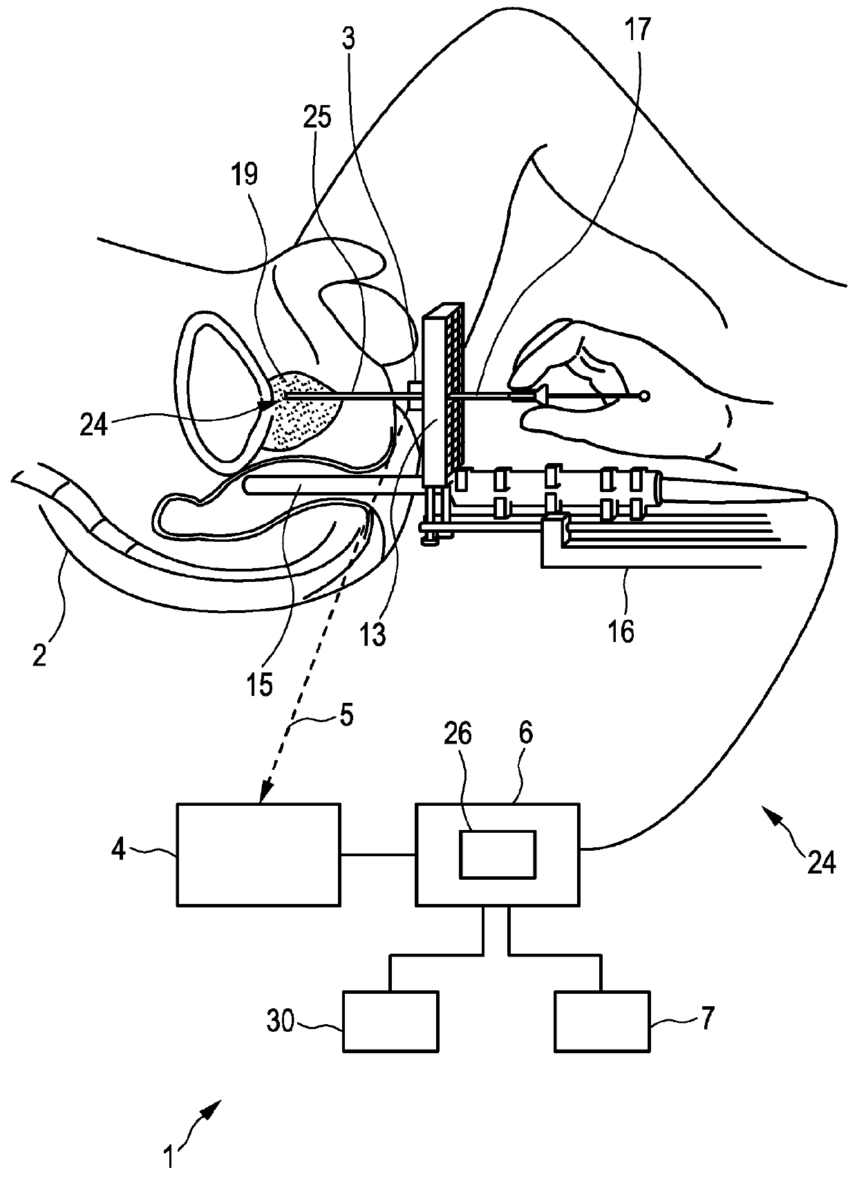
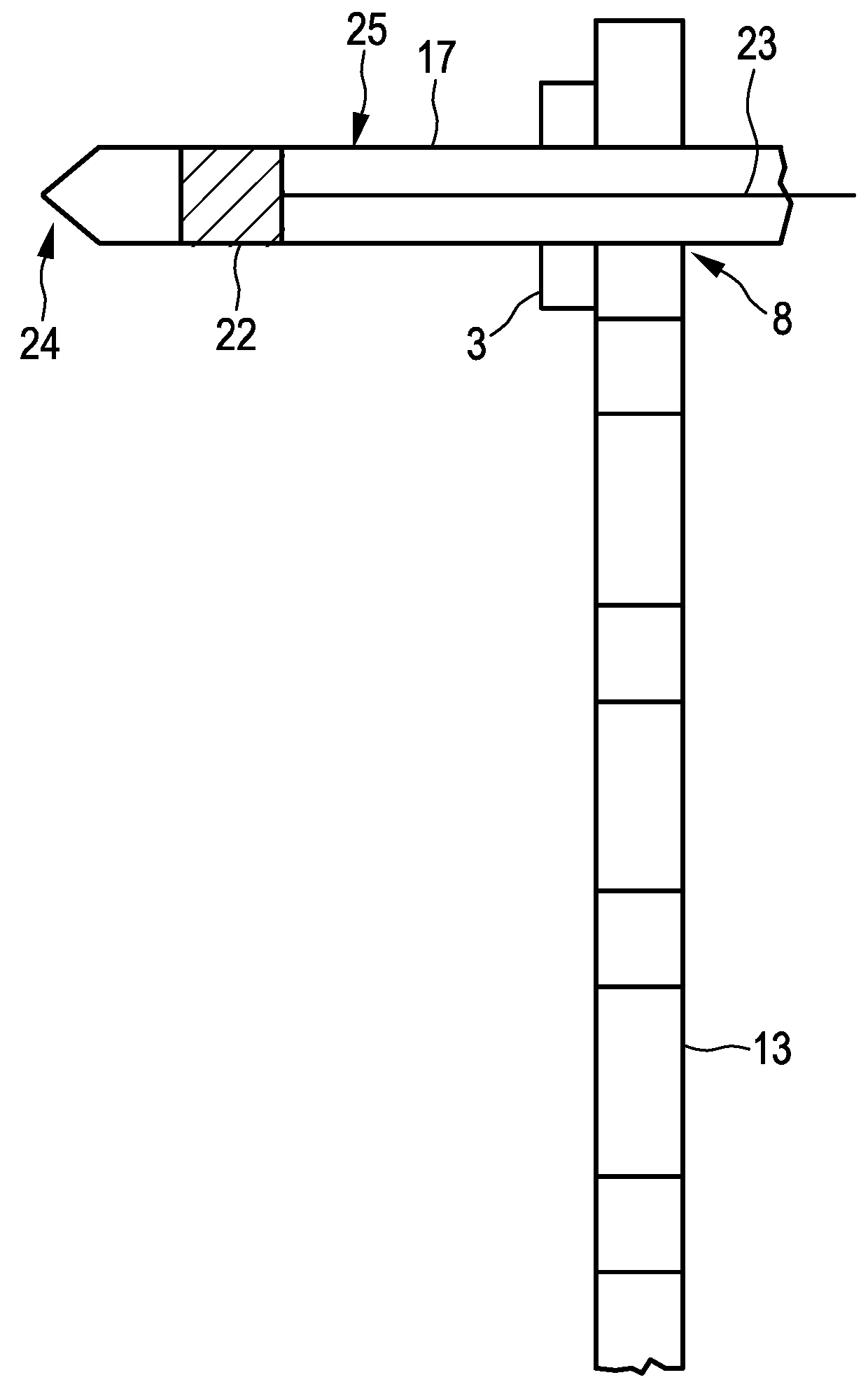
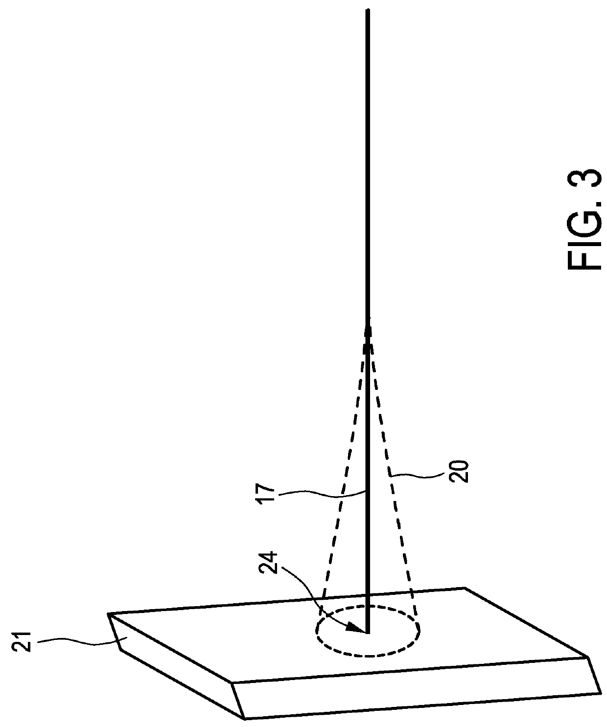
[0040]FIG. 1 shows schematically and exemplarily an embodiment of a brachytherapy system for performing a brachytherapy. The brachytherapy system 1 comprises an introduction element 17 for introducing a radiation source into a person 2. In this embodiment, the introduction element 17 is a needle, which is inserted into the prostate 19 of the person 2. During the insertion process an imaging apparatus 24 is used for imaging the introduction element 17 within the person 2.

[0041]The imaging apparatus 24 comprises a tracking unit 3, 4 for tracking the location of the introduction element 17 within the person 2, an imaging unit 6, 16 for generating an image showing an inner part of the person 2, which includes the tracked location of the introduction element 17, based on the tracked location, and a display 7 for displaying the image.

[0042]The introduction element 17 is manually inserted into the person 2, in particular, into the prostate 19, under image guidance. In particular, the imagi...


PUM


Abstract

The invention relates to an imaging apparatus (24) for imaging an introduction element (17) like a needle or a catheter for performing a brachytherapy or a biopsy. A tracking unit (3, 4) tracks the location of the introduction element within a living being (2), an imaging unit (6) like an ultrasound imaging unit generates an image showing an inner part of the living being, which includes the tracked location of the introduction element, based on the tracked location, and a display (7) displays the image. During the brachytherapy or biopsy the display can always show the introduction element, without requiring a manual control. For instance, it is not necessary that a physician manually controls the position and image plane of the imaging unit. This allows for an accurate and fast insertion of the introduction element into the living being such that a target region is reliably reached.

Description

FIELD OF THE INVENTION[0001]The invention relates to an imaging apparatus, an imaging method and an imaging computer program for imaging an introduction element like a catheter or a needle within a living being during a brachytherapy or a biopsy. The invention relates further to a system for performing a brachytherapy or a biopsy comprising the imaging apparatus.BACKGROUND OF THE INVENTION[0002]In low-dose rate (LDR) brachytherapy and high-dose rate (HDR) brachytherapy an introduction element like a catheter or a needle for introducing a radiation source is inserted into a person by a physician under ultrasound imaging guidance, in order to treat an inner region of the person with radiation emitted by the radiation source. During the insertion process the physician has to manually control the position and image plane of an ultrasound transducer, which leads to inaccuracies in imaging such that the tip of the introduction element is not always visualized accurately relative to a targ...

Claims


Application Information

Patent Timeline
Patent Type & Authority Applications(United States)
CPCA61B19/5244A61B2019/5251A61B2019/5261A61N2005/1012A61B2019/5263A61B2576/00A61B2010/045A61B2019/5265A61B8/0841A61B8/12A61B8/4209A61B8/465A61B8/469A61B8/483A61B8/523A61B10/0241A61B2017/3411A61N5/1027A61N5/1049A61N2005/1051A61N2005/1058A61B8/4245A61B2034/2063A61B34/20A61B2034/2051A61B2034/2059A61B2034/2061A61B2034/2065A61B2090/378
Inventor TAHMASEBI MARAGHOOSH, AMIR MOHAMMADBHARAT, SHYAMDEHGHAN MARVAST, EHSANPARTHASARATHY, VIJAY
Owner KONINKLJIJKE PHILIPS NV
Why Eureka
Try Eureka