Seal structure, chain case, and seal structure formation method

Inactive Publication Date: 2009-10-29
TOYOTA JIDOSHA KK
View PDF3 Cites 2 Cited by
  • Summary
  • Abstract
  • Description
  • Claims
  • Application Information

AI Technical Summary

Benefits of technology

[0048]By fastening the third member to the first member and second member in this manner, the periphery of the liquid sealing material guiding recessed portion eventually enters a state of surface contact such that liquid sealing material applied directly to the liquid sealing material guiding recessed portion and the liquid sealing material that flows into the liquid sealing material guiding recessed portion run out of places to escape to and increase in pressure, as described above in the first aspect of the invention. As a result, a large amount of the liquid sealing material is caused to flow forcefully into the interval sandwiching the gasket, and therefore, the liquid sealing material can flow into the innermost portion of the interval so as to reach the end portion of the gasket reliably.
[0049]Hence, a seal structure with which the liquid sealing material can flow sufficiently to positions requiring sealing during fastening of the third member such that a reliable seal is achieved can be realized. Further, the liquid sealing material guiding recessed portion may be formed such that in a width direction of the interval between the first member and the second member, the internal region of the

Problems solved by technology

When the liquid sealing material does not extend to and seal the end portion of the gasket, lubricating oil in the chain case passes between the cylinder head and the cylinder block through a gap between the gasket end portion and the liquid sealing material and lea

Method used


Image

  • Seal structure, chain case, and seal structure formation method
  • Seal structure, chain case, and seal structure formation method
  • Seal structure, chain case, and seal structure formation method

Examples


first embodiment

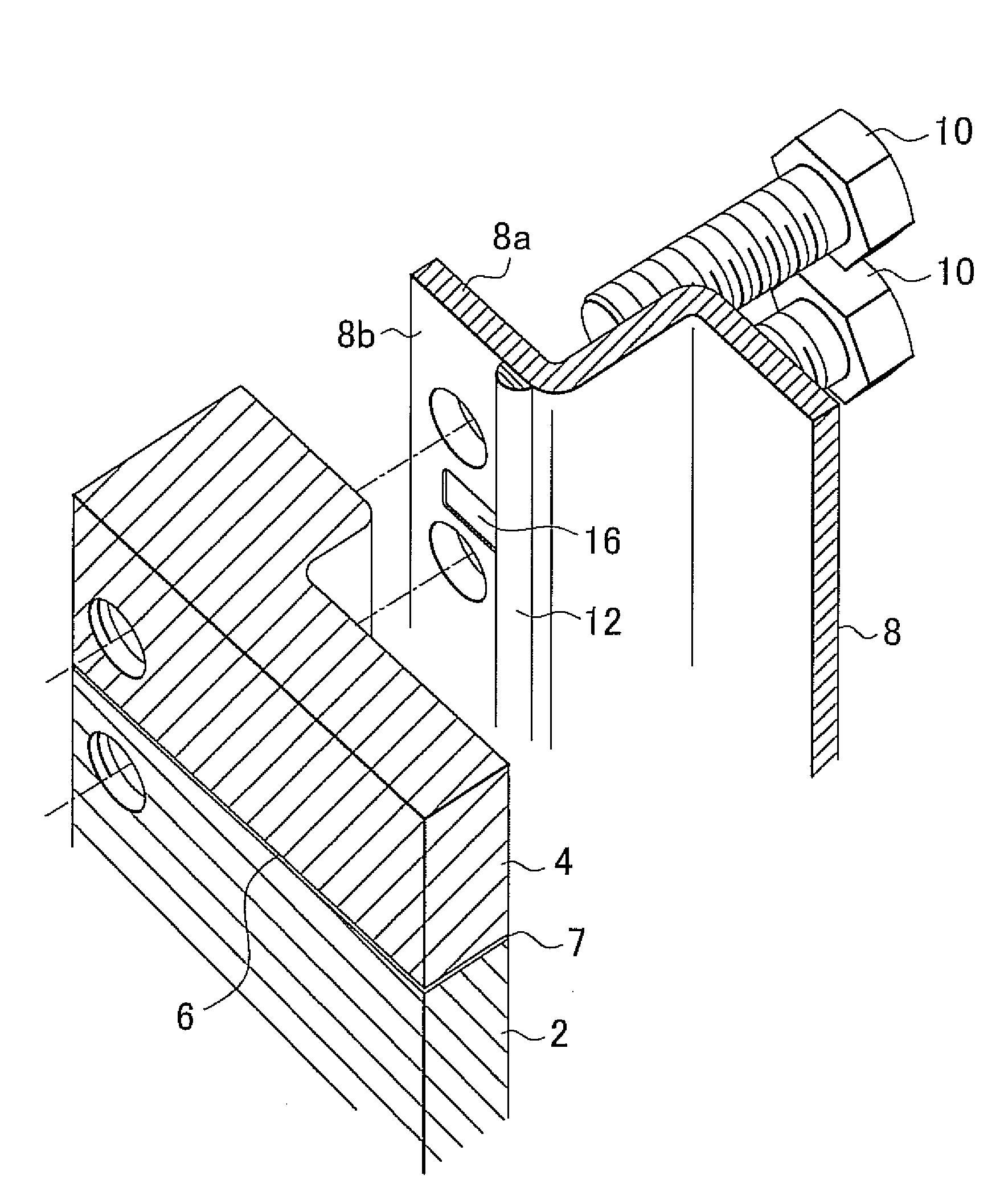
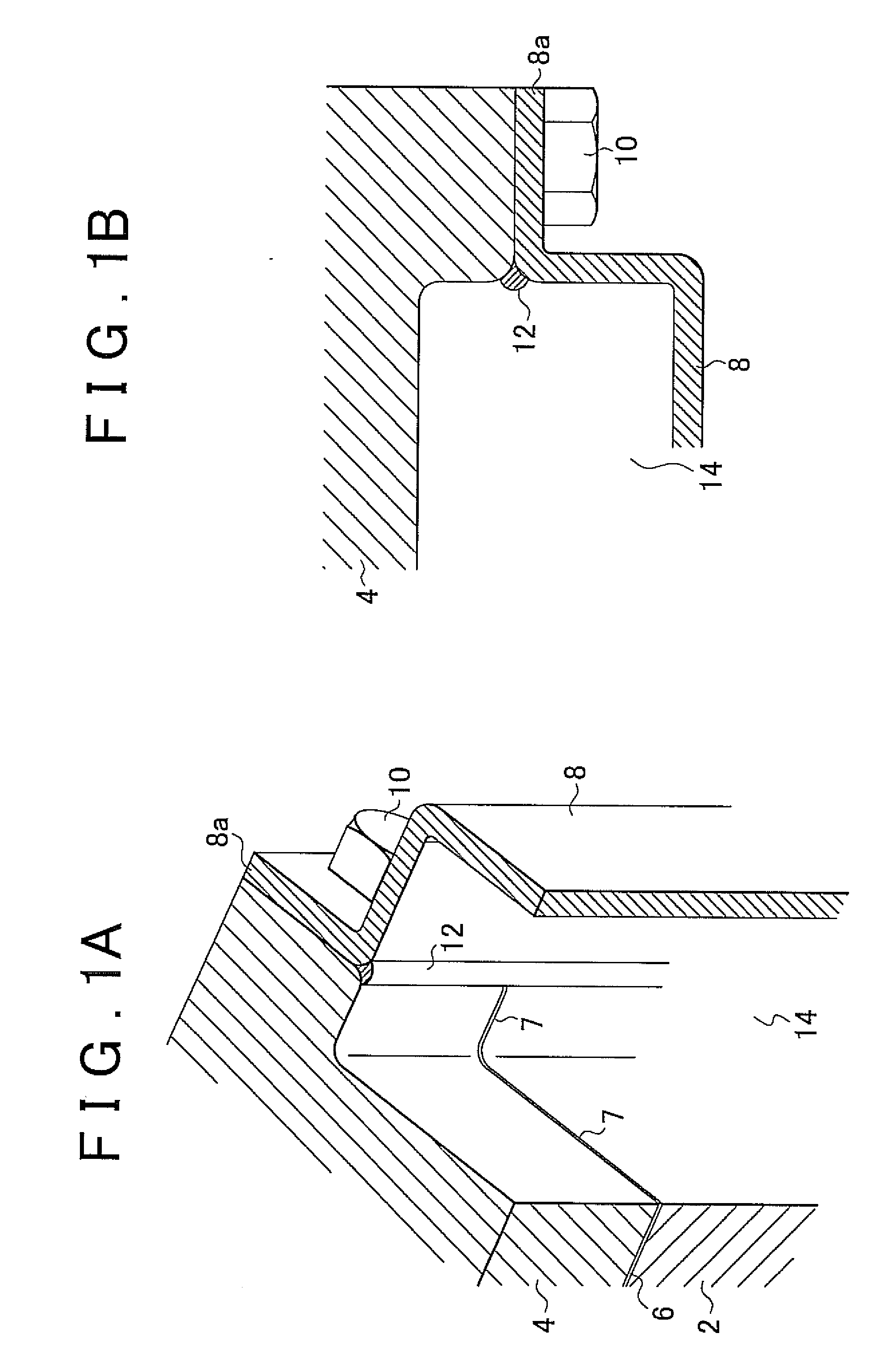
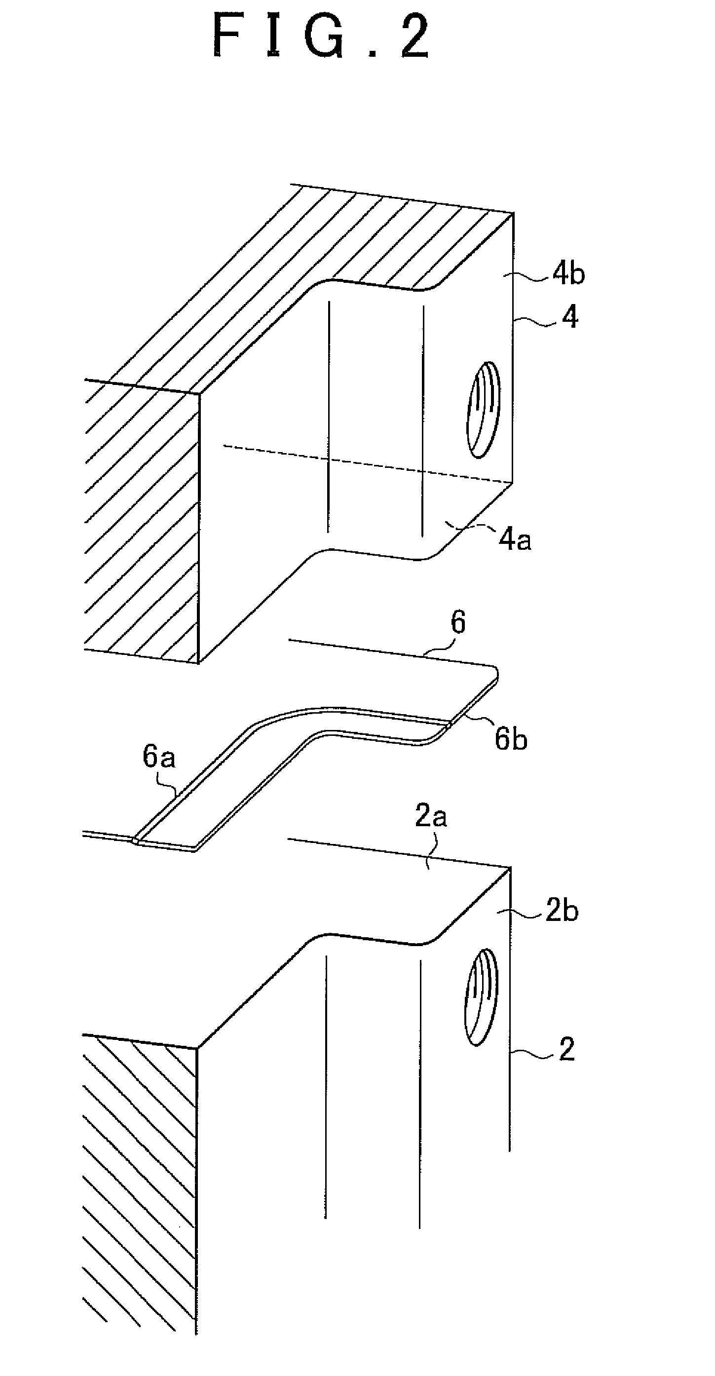
[0073]FIGS. 1A and 1B are constitutional diagrams showing the main parts of a seal structure for an internal combustion engine to which a seal structure according to a first embodiment of the invention is applied. FIG. 1A is a cut-off perspective view, and FIG. 1B is a plan view of the cut-off state shown in FIG. 1A. A cylinder head 4 is bolted to a cylinder block 2 via a gasket 6. A chain case 8 is fastened to an end face of the cylinder block 2 and an end face of the cylinder head 4 in the fastened state so as to cover an interval 7 in which the gasket 6 is sandwiched.

[0074]The chain case 8 is fastened to the cylinder block 2 and cylinder head 4 side by bolts 10 inserted into a flange portion 8a thereof. A liquid sealing material 12 is applied between the flange portion 8a of the chain case 8 and the respective end faces of the cylinder block 2 and cylinder head 4, including the interval 7, prior to fastening. During fastening by the bolts 10, the liquid sealing material 12 receiv...

second embodiment

[0088]As shown in FIGS. 8A and 8B, a second embodiment of the invention differs from the first embodiment in that a liquid sealing material guiding recessed portion 116 is formed as a substantially triangular recessed portion. All other constitutions are identical to their counterparts in the first embodiment. FIG. 8A is a cut-off perspective view, and FIG. 8B is a principal front view.

[0089]As shown in FIG. 9, the liquid sealing material guiding recessed portion 116 is formed such that in a width direction of an interval 107 between a cylinder block 102 and a cylinder head 104 (an X direction in FIG. 8B), the internal region thereof is narrower in a thickness direction of the interval 107 (a Y direction in FIG. 8B) on the side of the bead portion of a gasket 106 than the side (inner side) coated with a liquid sealing material 112.

[0090]Hence, when a seal surface 108b of a flange portion 108a is pressed against the seal surfaces of the cylinder block 102 and the cylinder head 104 an...

third embodiment

[0097]As shown in FIGS. 11A and 11B, in a third embodiment of the invention, a liquid sealing material guiding recessed portion 216, 266 varies in depth toward the outer side of a chain case 208, 258. FIG. 11A shows a case in which the depth of the liquid sealing material guiding recessed portion 216 is increased toward the outer side such that an application position of a liquid sealing material 212 corresponds to a shallow side and the liquid sealing material guiding recessed portion 216 deepens from this application position toward the bead portion of the gasket. FIG. 11B shows a case in which the depth of the liquid sealing material guiding recessed portion 266 is reduced toward the outer side such that the application position of a liquid sealing material 262 corresponds to a deep side and the liquid sealing material guiding recessed portion 266 becomes shallower from the application position toward the bead portion of the gasket. All other constitutions are identical to their ...


PUM

PropertyMeasurementUnit
Thicknessaaaaaaaaaa
Widthaaaaaaaaaa

Abstract

A chain case disposed opposite an interval between a cylinder block and a cylinder head sandwiching a gasket includes a liquid sealing material guiding recessed portion that opposes the interval and is entirely surrounded by a seal surface. During seal structure formation, a large amount of a liquid sealing material is caused to flow forcefully toward the interior of the interval when an operation is performed to fasten the chain case to the cylinder block and the cylinder head such that the liquid sealing material flows to the innermost portion of the interval, and as a result, the liquid sealing material can reach an end portion of the gasket reliably. Hence, the liquid sealing material can flow sufficiently to positions requiring sealing, whereby lubricating oil leakage from the interior of the chain case can be prevented.

Description

INCORPORATION BY REFERENCE[0001]The disclosure of Japanese Patent Application No. 2008-113889 filed on Apr. 24, 2008 including the specification, drawings and abstract is incorporated herein by reference in its entirety.BACKGROUND OF THE INVENTION[0002]1. Field of the Invention[0003]The invention relates to a seal structure for a part which includes an interval between a first member and a second member sandwiching a gasket, and in which a third member is disposed to face the first member and second member via a liquid sealing material, a chain case on which this seal structure can be used, and a seal structure formation method.[0004]2. Description of the Related Art[0005]A seal structure including an interval between two mated members, in which a third member is disposed via a liquid sealing material, or in other words a seal structure for a so-called three surface mating portion, is used as a seal structure for a chain case (also referred to as a chain cover) of an internal combus...

Claims


Application Information

Patent Timeline
IPC IPC(8): F02F11/00F02F7/00B21D53/84
CPCF02F2007/0078Y10T29/49297F16J15/14F16J15/062
Inventor KAWAMOTO, NAOYA
Owner TOYOTA JIDOSHA KK
Why Eureka
Try Eureka