Pressure detecting unit for a measuring device for measuring a pressure status value of a plant specimen, and method for manufacturing a pressure detecting unit

Active Publication Date: 2022-01-06
ROBERT BOSCH GMBH
View PDF0 Cites 0 Cited by
  • Summary
  • Abstract
  • Description
  • Claims
  • Application Information

AI Technical Summary

Benefits of technology

[0017]According to a further specific embodiment of the method in accordance with the present invention, the filling material is introduced into the opening of the frame from a front side defined by the contact surface of the frame. In this way, the opening is successively filled, starting at the mounting surface of the carrier substrate, by means of which a uniform filling is advantageously achieved, reducing the risk of the formation of air bubbles or other inclusions. The frame may optionally include ventilation channels extending from or defined by the inner surface, which further reduce the risk of air inclusions.
[0018]According to a further specific embodiment of the method in accordance with the present invention, it is provided that the frame is fastened to the carrier substrate in an integral manner, in particular by gluing, or in a form-fitting manner, in particular by a clip connection. An integral connection offers, in particular, the advantage that the fastening surface of the frame is particularly reliably sealed against the carrier substrate. A form-fitting connection may be mounted, for example, very quickly and easily.
[0019]According to one specific embodiment of the pressure detecting device in accordance with the present invention, it is provided that the inner surface defines a first diameter or a first cross-sectional area of the opening, in the area of the contact surface of the frame, in particular at the contact surface, and defines a second diameter or a second cross-sectional area of the opening, in the area of the fastening surface of the frame, in particular at the fastening surface, the second diameter or the second cross-sectional area being larger than the first diameter or the first cross-sectional area of the opening. The opening thus narrows from the carrier substrate or the fastening surface in the direction of the contact surface. The inner surface thus forms an undercut with respect to an axis situated perpendicularly to the contact surface. In this way, an obstacle is implemented by the inner surface, which counteracts a movement of the pressure coupling layer out of the opening. This is advantageous, in particular, if the contact surface is at a distance from the plant specimen. Particularly elastic or soft pressure coupling layers may thus be used, which cling very effectively to the plant specimen. The accuracy of the measurement results is increased thereby. Furthermore, the deformation of the pressure coupling layer is reduced when it is detached from the plant specimen, by means of which the risk of a damage to the sensor unit is decreased. In addition, the cross section or diameter of the opening, which expands from the contact surface in the di

Problems solved by technology

This reduces both the risk of damaging the plant and the risk of the sensor unit becoming damaged.
In this way, an obsta

Method used


Image

  • Pressure detecting unit for a measuring device for measuring a pressure status value of a plant specimen, and method for manufacturing a pressure detecting unit
  • Pressure detecting unit for a measuring device for measuring a pressure status value of a plant specimen, and method for manufacturing a pressure detecting unit
  • Pressure detecting unit for a measuring device for measuring a pressure status value of a plant specimen, and method for manufacturing a pressure detecting unit

Examples


Example

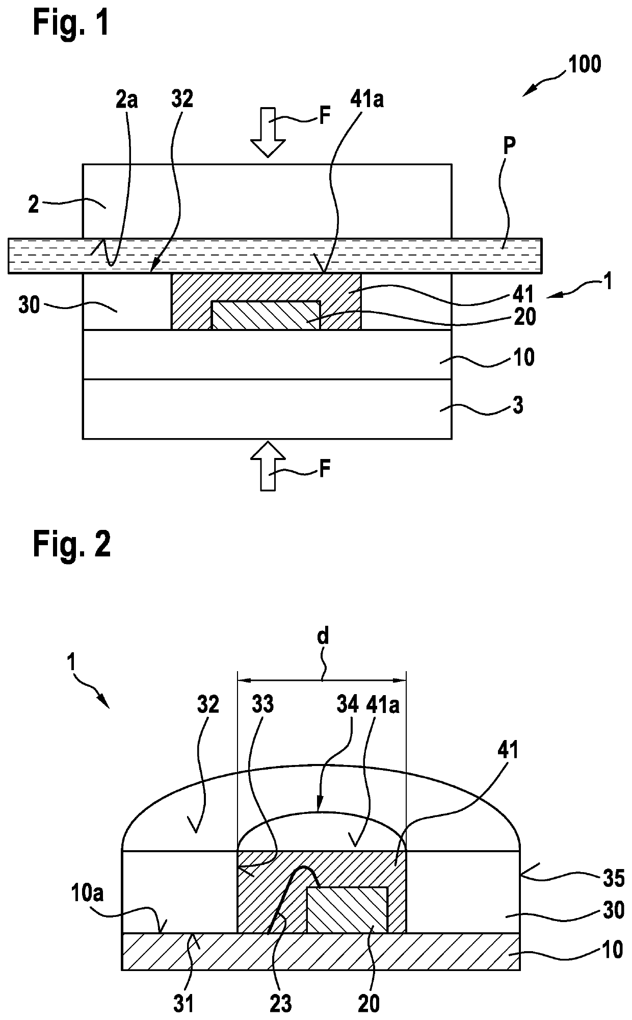
[0040]FIG. 1 schematically shows a sectional view of a measuring device 100 for measuring a pressure status value of a plant specimen P. The measured pressure status value is dependent on the so-called turgor pressure of plant specimen P. The hydrostatic overpressure in plant cells is referred to as turgor pressure and is a parameter representing an irrigation status of the plant. A high turgor pressure typically represents a high water content and thus a sufficient irrigation status of the plant, while a low turgor pressure indicates a low water content in the plant. Measuring device 100 illustrated as an example in FIG. 1 includes a pressure detecting unit 1 and a clamping unit 2. A magnet 3 may also be optionally provided.

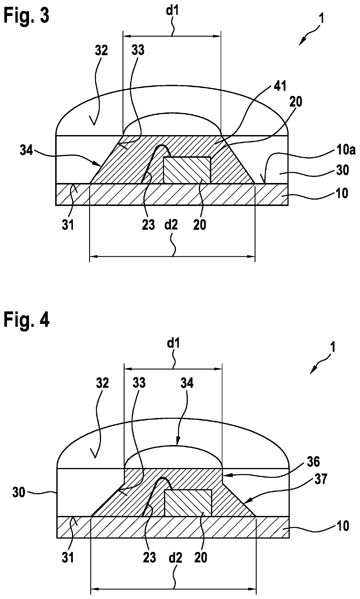
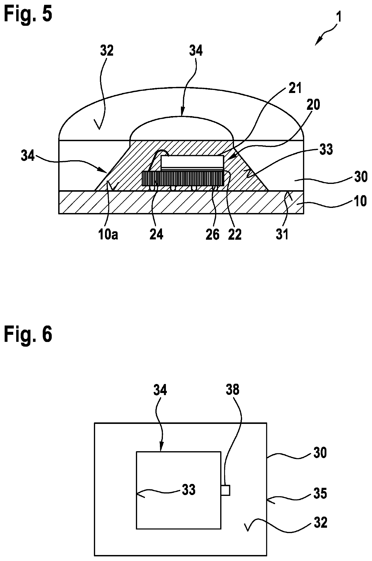
[0041]As schematically illustrated in FIG. 1, pressure detecting unit 1, which is explained in detail below, includes a carrier substrate 10, a sensor unit 20, a frame 30 and a pressure coupling layer 41.

[0042]Clamping unit 2 is implemented as a plate-shaped com...


PUM


Abstract

A method for manufacturing a pressure detecting unit for a measuring device for measuring a pressure status value of a plant specimen. The method includes mounting a sensor unit for detecting the pressure status value at a carrier substrate, fastening a frame to the carrier substrate, the frame including a fastening surface, a contact surface oriented opposite the fastening surface and an inner surface defining an opening and extending between the fastening surface and the contact surface, the frame being situated at the carrier substrate in such a way that the fastening surface faces the carrier substrate and the inner surface surrounds the sensor unit, and filling the opening of the frame with a filling material for forming an elastic pressure coupling layer. A pressure detecting unit for a measuring device for measuring a pressure status value of a plant specimen is also described.

Description

BACKGROUND INFORMATION[0001]Hydrostatic overpressure in plant cells is referred to as turgor pressure and represents a parameter for evaluating a status, in particular an irrigation status, of a plant. By detecting the turgor pressure or a turgor pressure-dependent pressure status value, for example at leaves of the plant, conclusions may be drawn as to whether the water supply of the plant is sufficient or an irrigation of the plant is necessary.[0002]To measure the turgor pressure or a variable representing the turgor pressure of a plant specimen, for example a leaf of the plant, measuring devices are being increasingly used, which are based on a non-destructive or non-invasive measuring method. For this purpose, the plant specimen is typically clamped with the aid of a clamping device, and a pressure signal representing the turgor pressure is registered with the aid of a sensor unit.[0003]German Patent Application No. DE 10 2006 043 058 A1 describes a measuring device for measuri...

Claims


Application Information

Patent Timeline
IPC IPC(8): G01L11/00G01L19/14A01G7/00
CPCG01L11/004A01G7/00G01L19/147G01L19/0627H01L2224/73265H01L2224/32225H01L2924/181H01L2224/48091H01L2224/48227H01L2924/15311H01L2924/00012H01L2924/00014H01L2924/00G01N33/0098G01L9/008
Inventor BOECKER, MATTHIAS
Owner ROBERT BOSCH GMBH
Why Eureka
Try Eureka