Resin composite with overloaded solids for well sealing applications

Active Publication Date: 2018-12-13
WILD WELL CONTROL
View PDF2 Cites 3 Cited by
  • Summary
  • Abstract
  • Description
  • Claims
  • Application Information

AI Technical Summary

Benefits of technology

[0013]Herein, a composite sealing material delivered to a sealing location in fluid slurry form, and in which constituents thereof react to form a solid sealing plug in the sealing location, is composed of a fluid sealing material, such as epoxy or Portland cement, and one or more solids, wherein the solids migrate under the influence of gravity when the slurry is in a static, i.e., non-mixing or pumped, mode and the resulting slurry in fluid form, and the sealing plug in solid form, becomes segregated into a solids depleted portion from which solids have migrated, and a solids enhanced portion physically below the solids depleted portion into which solids have migrated from the solids depleted portion. The resulting static slurry, and sealing plug has a lower portion having a greater quantity of solids therein than is mixable and pumpable to the sealing location in the well when using standard oilfield equipment, and the resulting properties of the solids enriched portion yield a more reliable seal with a lower maximum exothermic reaction based temperature rise, and a shorter time from the exothermic reaction induced peak temperature to the sealing material reaching the temperature of the ambient surrounding the sealing location, as compared to a sealing composite wherein solids are relatively uniformly mixed therein at or below the limit at which the resulting fluid slurry can be pumped to the sealing location using standard oilfield equipment. Thus, the seal designer, and the sealing operation operator, can deliver a composite sealing material in fluid slurry form to a sealing location with a high degree of confidence that the fluid slurry sealant will, upon hardening, seal the well.
[0014]After the solids settle or migrate to form the solids depleted and solids enhanced portions of the fluid slurry, the sealing material base cures and hardens to form a solid plug in the well. After solids migration, and epoxy hardening, the upper portion of the solid plug consists of epoxy with a very low concentration of solids, or no solids at all, therein. The lower portion of the sealing plug includes the solids of the upper, now depleted, region which have settled or migrated thereinto, in addition to the solids originally therein when the fluid slurry was located in the sealing location, and thus the solids content cons

Problems solved by technology

The leaks best suited to being repaired using epoxy resin, as opposed to using additional cement sealant, are usually small in cross-sectional area and difficult to access which makes the use of Portland cement, the traditional sealant for sealing well leaks, ineffective.
One detrimental feature of epoxy is that the setting of epoxy, i.e., the hardening thereof from a liquid (fluid) to a solid form, is an exothermic chemical reaction, and because the epoxy has low thermal conductivity and low heat capacity, it experiences an increase in temperature after the resin and hardener are intermixed and the exothermic reaction there between initiates and progresses.
Temperature increase in the resin during the epoxy setting reaction is detrimental to forming a satisfactory epoxy seal in a well.
Epoxy thermal properties exacerbate these detrimental effects.
First, epoxy in both a fluid and a solid state has a high coefficient of thermal expansion.
Second, the heat capacity of epoxy in both the fluid and the solid state is low; considerably lower than that of steel, Portland cement, or the subterranean earth formations around the well casing.
Third, the thermal

Method used


Image

  • Resin composite with overloaded solids for well sealing applications
  • Resin composite with overloaded solids for well sealing applications
  • Resin composite with overloaded solids for well sealing applications

Examples


application example

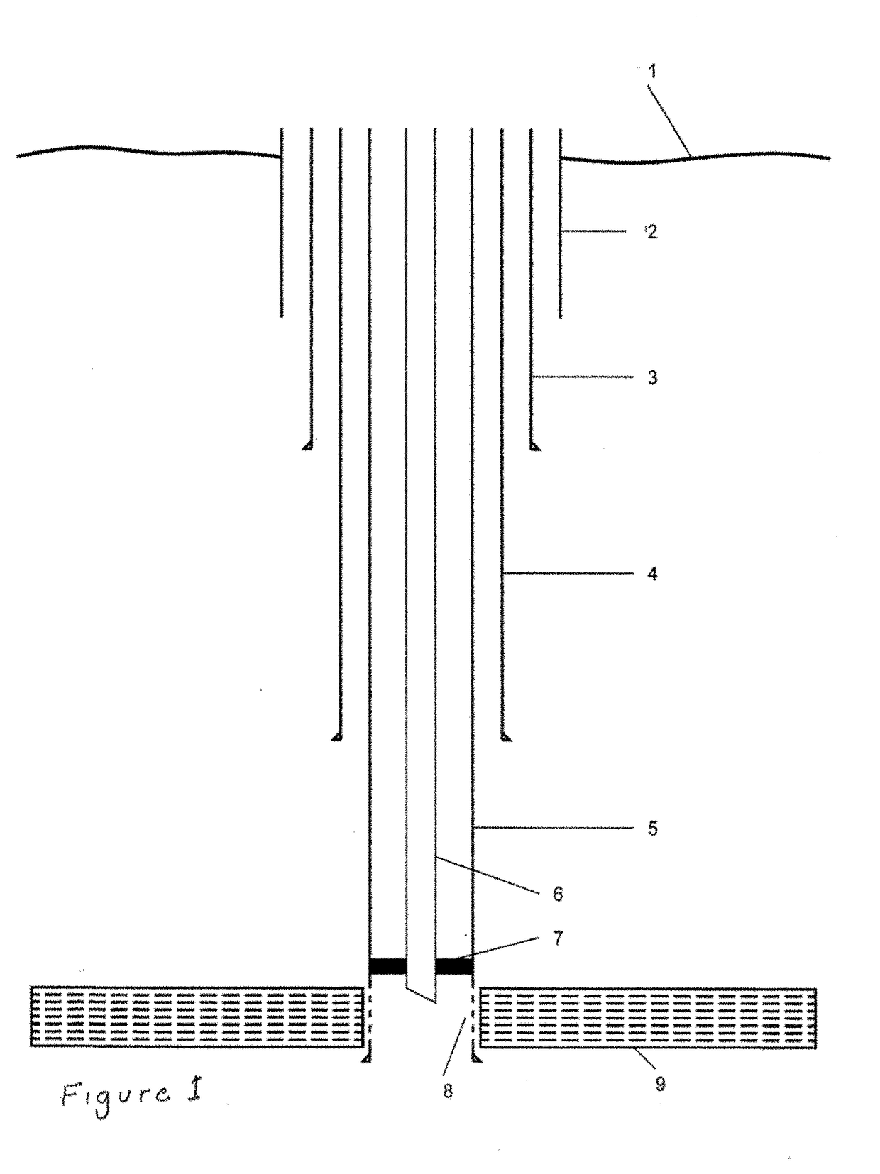
[0103]As shown schematically in FIG. 1, an offshore well targeted for abandonment includes a plurality of telescoping casings 2 extending from the sea floor 1, or slightly thereabove, to the producing formation 09 located inwardly of the earth. The distance between the seafloor and the producing formation(s) is on the order of thousands of feet, whereas the diameter of the casings is on the order of several feet to less than one foot. The series of telescoping casings 02 through 05 were previously cemented in place in the drilled well bore by cement extending between at least portions of the lengths thereof and the adjacent earth formations of the drilled bore, and cement is also located in at least a portion of the annulus where the smaller casing extends inwardly of an overlying larger casing. A production tubing 06 is isolated from the casings by a production packer 07. The casing extending through, or into, a producing formation includes perforations 08 therethrough to provide a...


PUM

PropertyMeasurementUnit
Temperatureaaaaaaaaaa

Abstract

Provided herein are methods of formulating a sealant to span an opening and form a seal with surfaces across the opening including selecting a fluid material capable of contacting and adhering to the surface of the opening and which reacts to form a solid material as a result of a thermal reaction, and selecting and intermixing one or more solids with the fluid material to form a composite, wherein the solids migrate within a column of the composite sealant before the composite sealant cures from a fluid to a solid and bonds to the surfaces of the opening, and the change in volume of the lower portion of the lower portion composite sealant into which the solids have migrated, as the temperature thereof changes during curing, is insufficient to cause it to pull away from the surfaces of the opening or fail internally.

Description

BACKGROUND OF THE INVENTIONField of the Invention[0001]Embodiments hereof relate to the sealing of wells used to produce hydrocarbons from subsurface formations penetrated thereby. More particularly, embodiments hereof relate to the formulation of sealants used to seal wells, and the application thereof at a location within a well to be sealed.Description of the Related Art[0002]Epoxy (resin introduced as a fluid and hardened in situ) is used as a specialty sealant in the upstream petroleum industry for repairing leaks originating in well barriers, i.e., to repair leaks in a cement sheath previously formed between sections of casing of different diameters, previously formed around the casing to seal between the casing and the earth of the drilled well bore, and previously formed at other locations of the well or casing. The leaks best suited to being repaired using epoxy resin, as opposed to using additional cement sealant, are usually small in cross-sectional area and difficult to ...

Claims


Application Information

Patent Timeline
IPC IPC(8): C09K8/508E21B33/13E21B33/12
CPCC09K8/5086E21B33/12E21B33/13C04B28/04C09K8/426C09K8/44C09K8/467C09K8/5045C09K8/508C09K8/516C04B26/14C09D163/00C04B14/024C04B14/06C04B14/304C04B14/324
Inventor SABINS, FREDDIE LYNNLEAL, JORGE ESTEBANWATTERS, LARRY THOMAS
Owner WILD WELL CONTROL
Why Eureka
Try Eureka